 Kevin Kessler
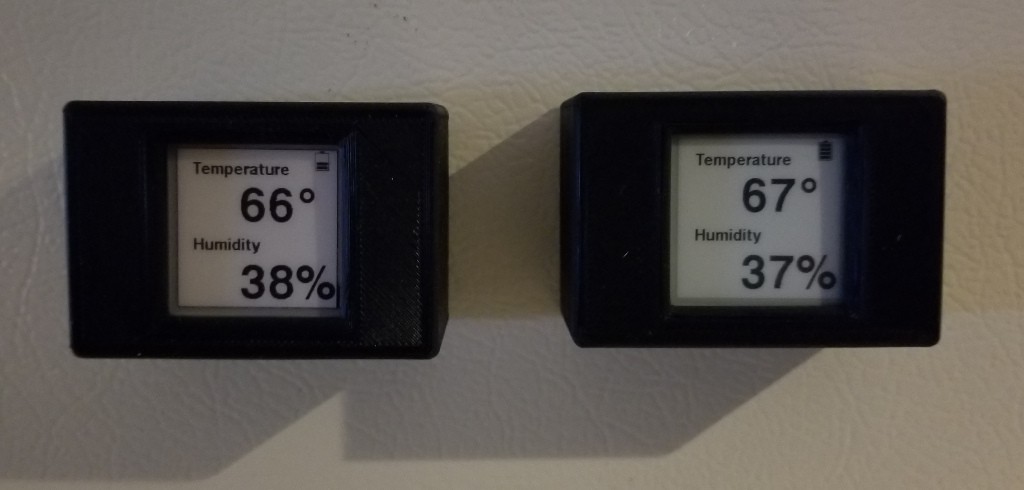
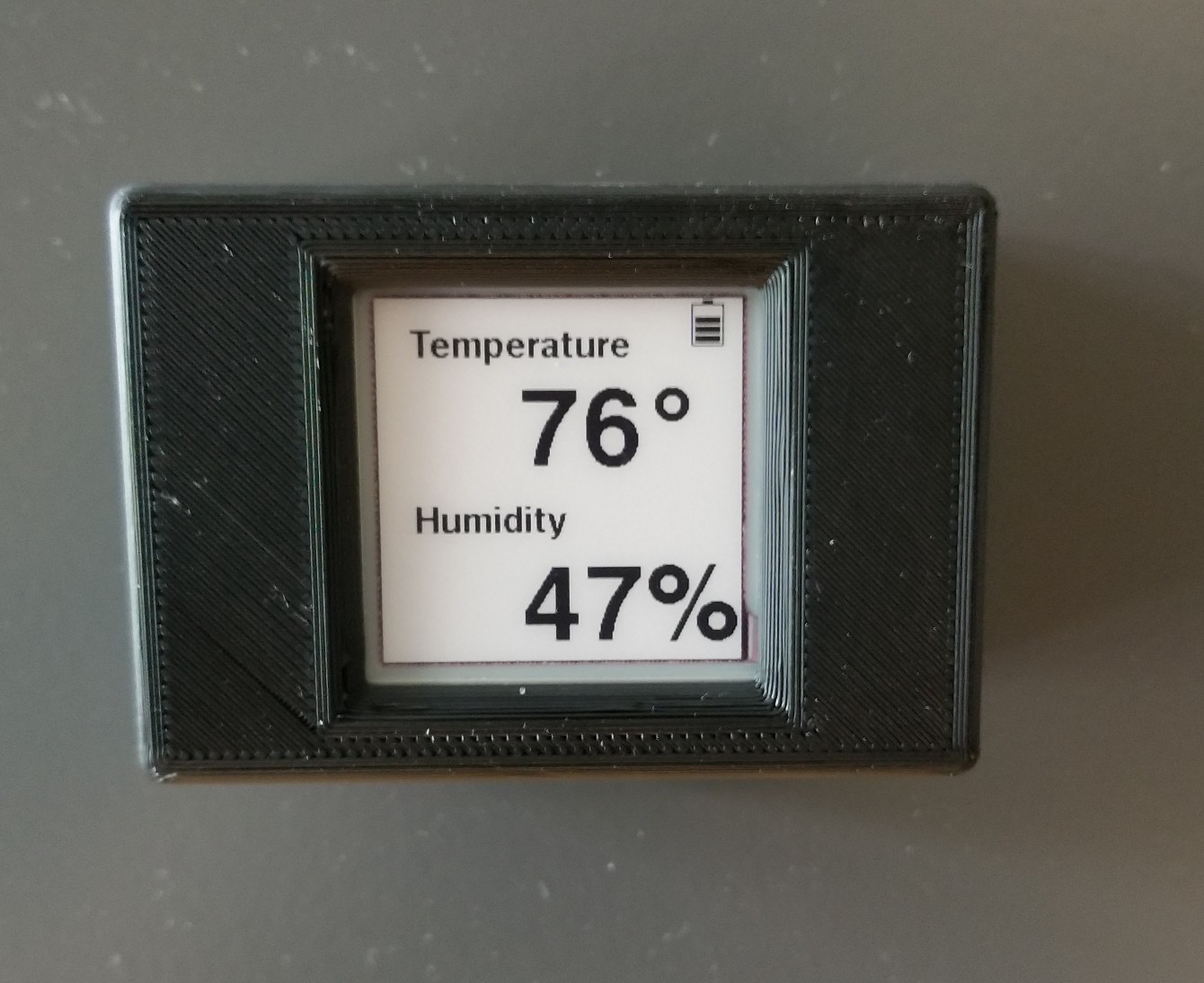
The initial version of the software has no attempt to conserve power; it is just a functional version, which reads the temperature and humidity counters from the I2C interface, calculates the actual temperature and humidity, and displays them on the ePD using the code from Waveshare's wiki. The Waveshare code had to be slightly modified so that the black and red frame data are loaded into the device separately. The original function took 2 5000 byte buffers of display data, which will not fit in the 8K of SRAM on this device, so I split the function into a load black buffer, and a load red buffer, and reused the 5000 byte buffer for those calls. This version of the code is located at this project's github location with the tag NonOptimized.
I use the STM32CubeMX to generate the framework source code in a Makefile package, and use Eclipse to write the code. OpenOCD and an ST-Link V2 is used to program the device.
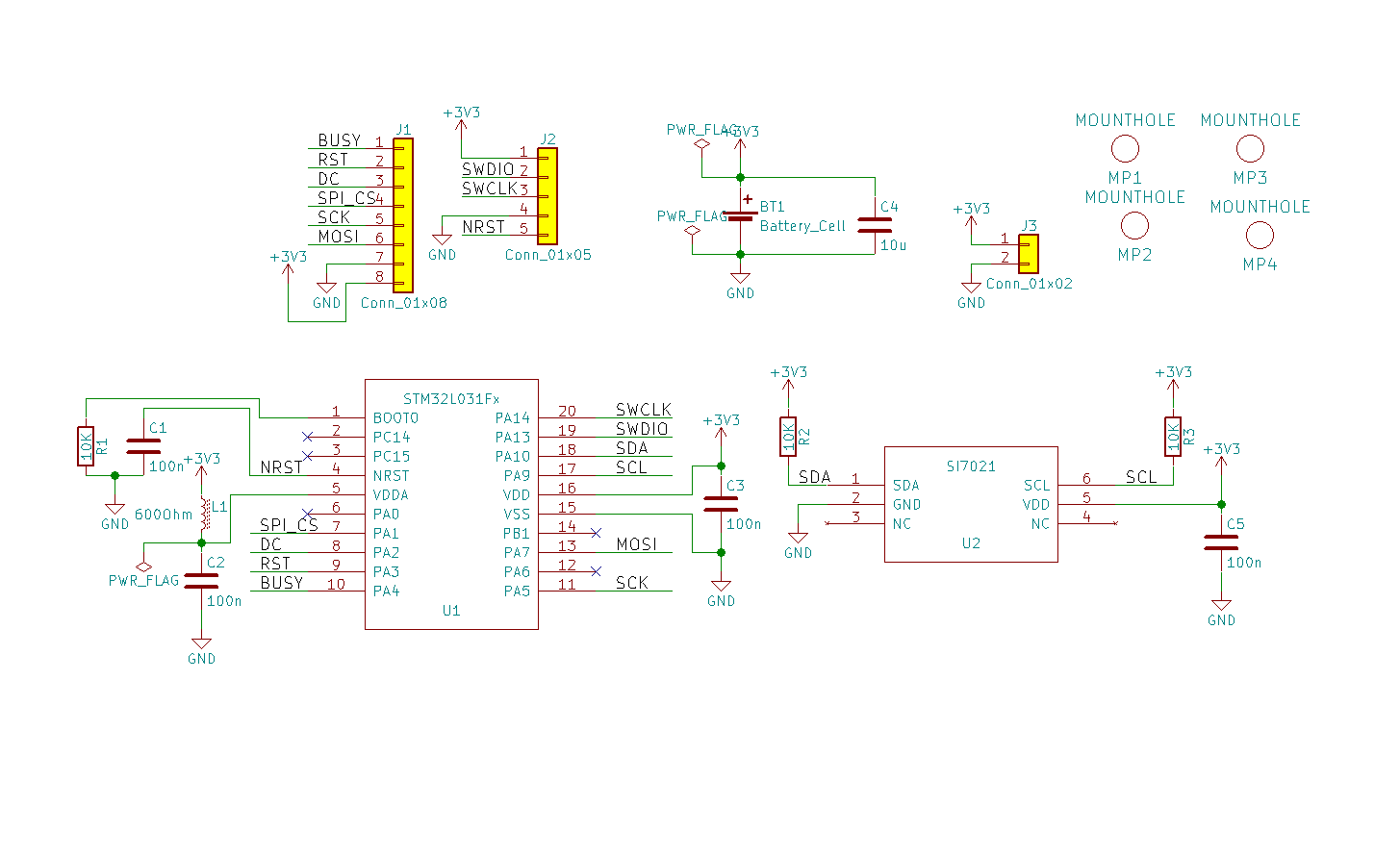
The schematic of the device:
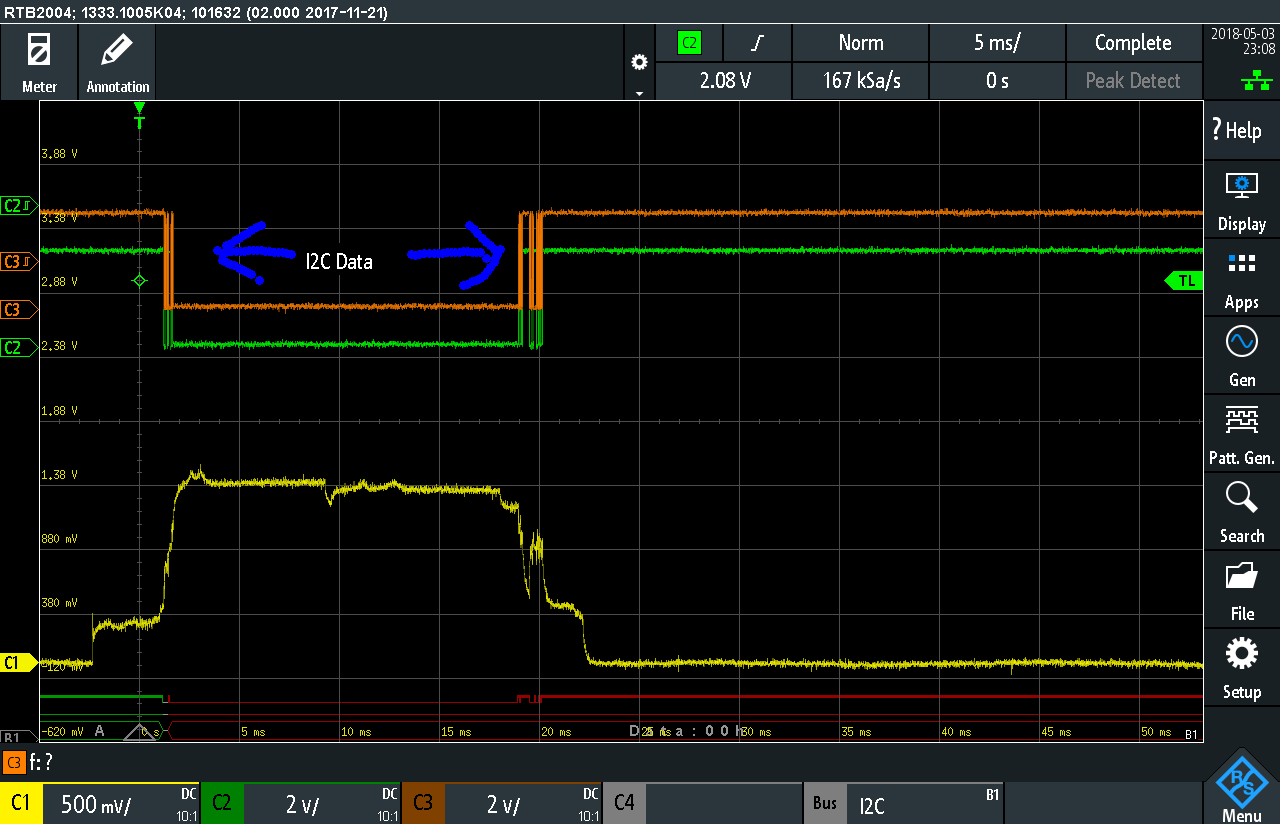
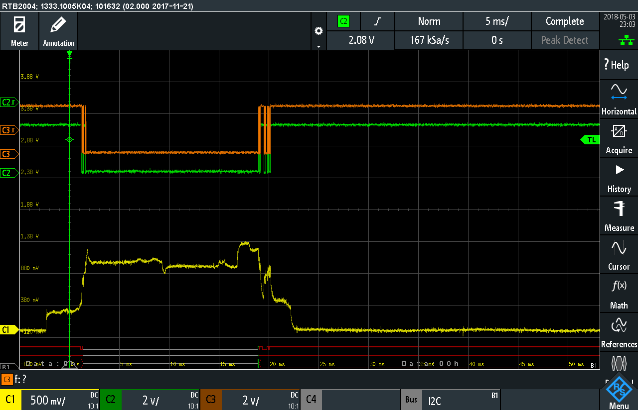
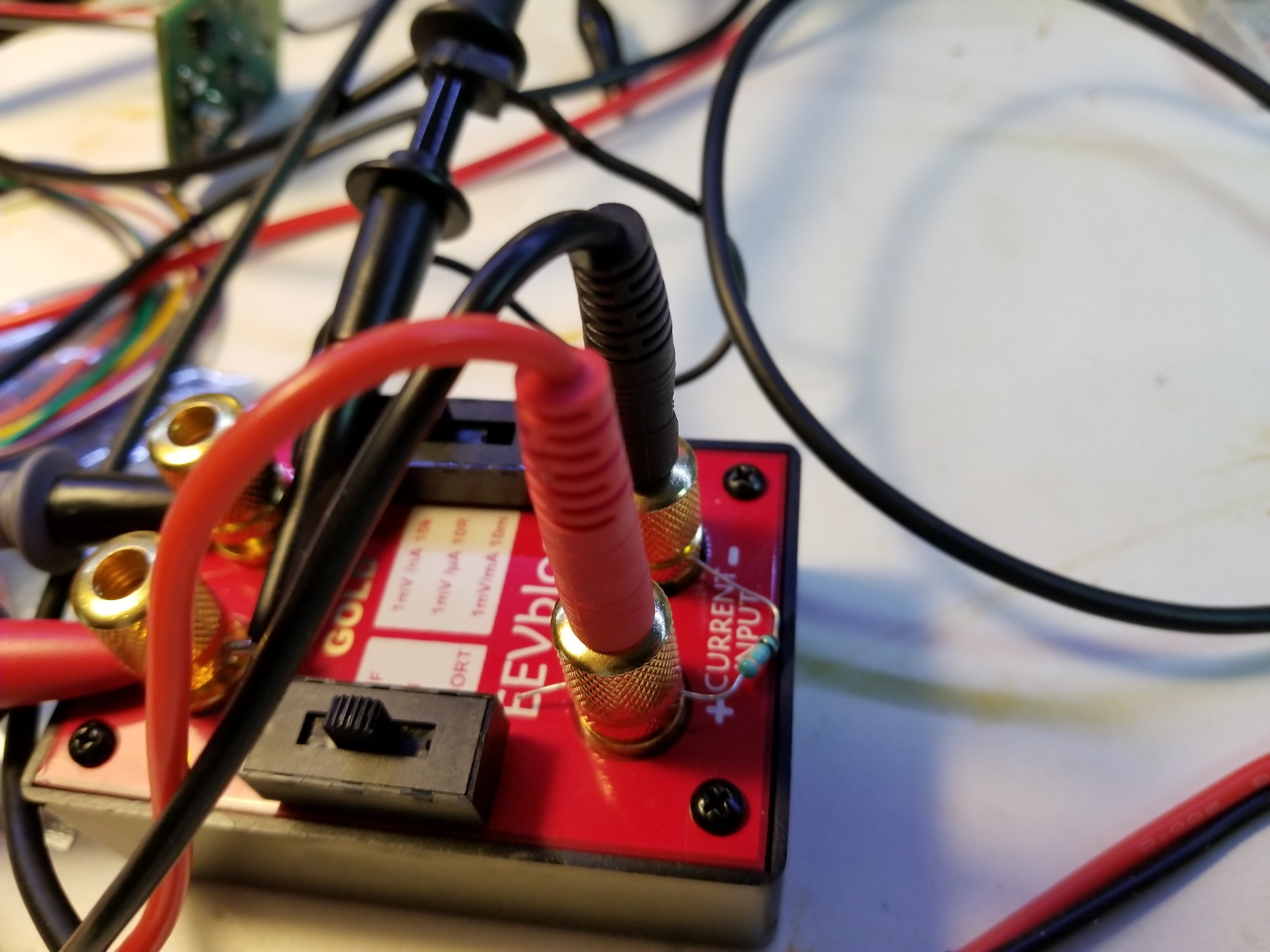
To measure current consumption, I use a Dave Jones uCurrent Gold, monitored by a Siglent SDM3055 multimeter. A python script pulls the current data from the meter at a rate of about 5 measurements per second, and that data is put into a spreadsheet for analysis.
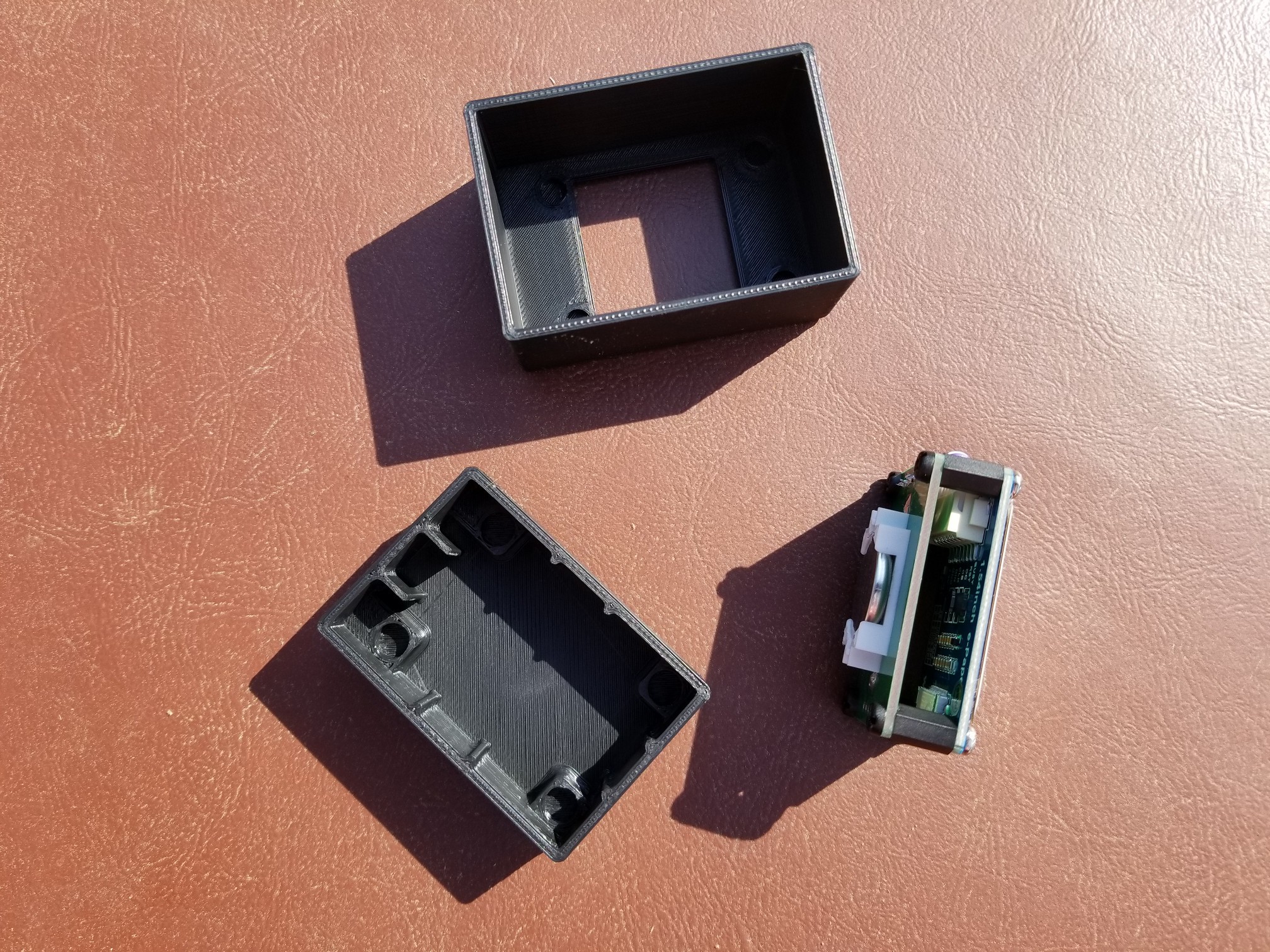
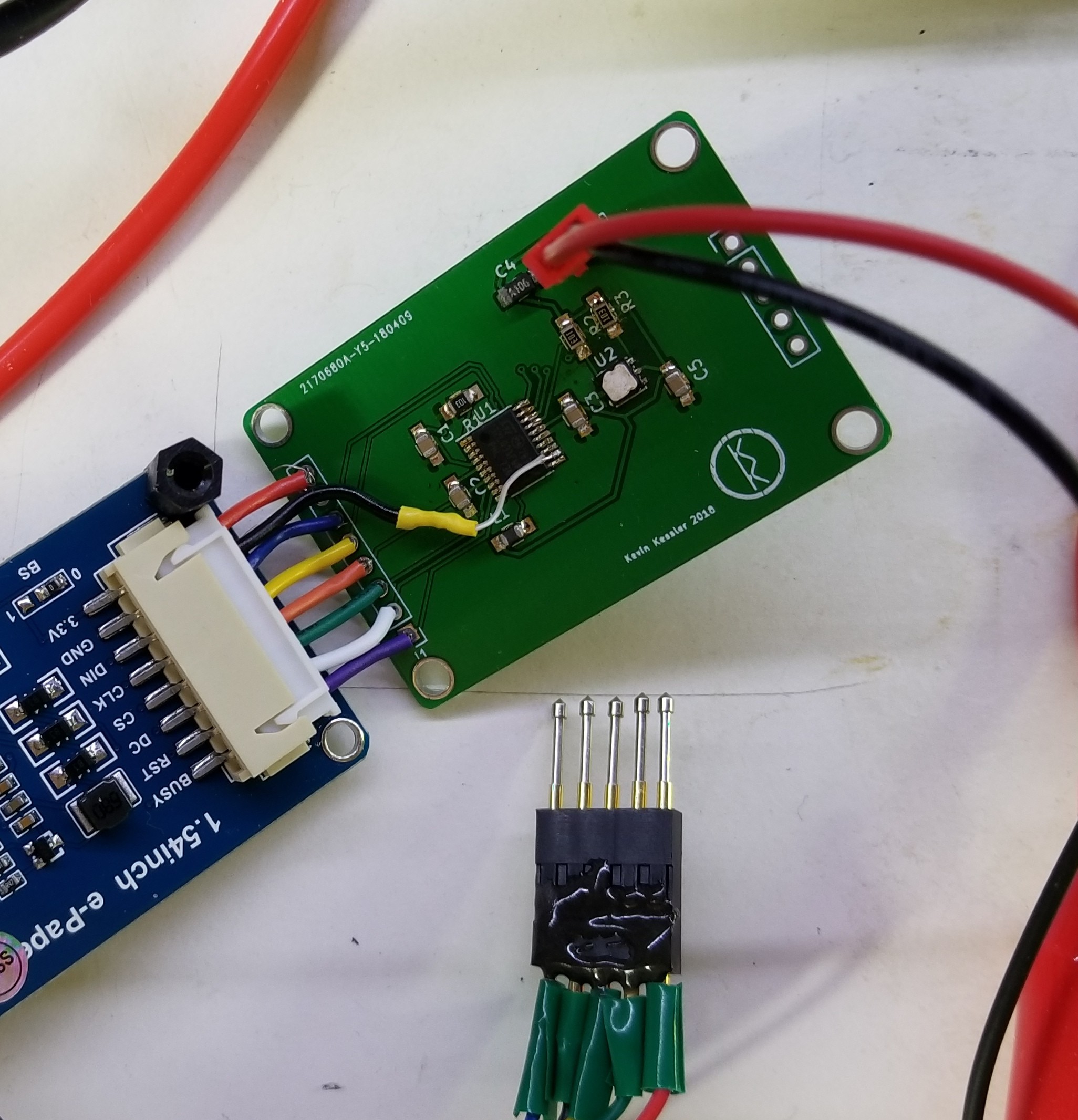
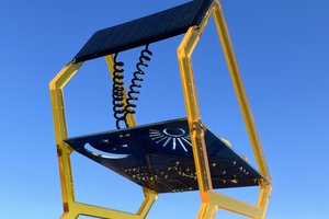
The current breadboard setup:
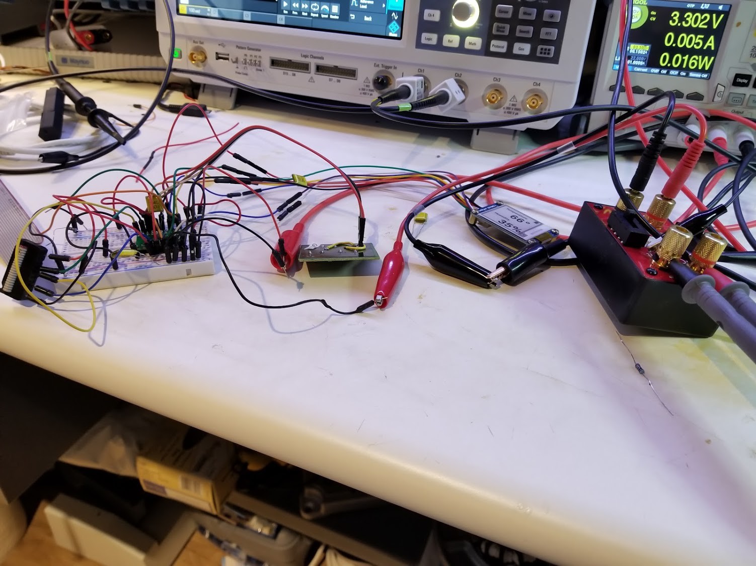
I have a proper PCB for this project in transit from China as I write this, which should clean up the test setup quite a bit.


 Gabor
Gabor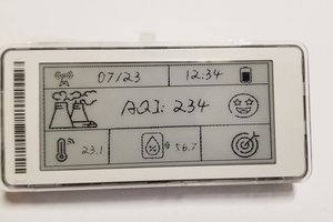
 Nick Sayer
Thanks for your excellent write-up. I will be building something similar, but with an nRF52840 to also send the temperature over BLE. I'm sure your learnings will help me.