 Kevin Kessler
I got my PCBs from China, and I threw one in the toaster over, to build my device. I was ready to connect the display when I found a problem. The connector on the Waveshare ePaper Display is an 8 pin JST XH, the same ones used as balance connectors on Lipo chargers, so I bought some 8 cell balance cables from Aliexpress a few weeks ago for this project. Doh, 8 cells charging cable have 9 pins, and they just aren't going to fit in the 8 pin connector on the ePaper display. While I prefer just buying professionally crimped connectors, I was in a bind, so I order a small kit of JST XH crimp connectors with Amazon prime. When they come in I'll finish the build.
All was not lost, though, because you always get a bunch of extra PCBs when you order them, so I just installed all the capacitors and the bead on a PCB, to measure the leakage current of the capacitors. Reading the Jack Ganssle article on real world low power uC, he states the coupling capacitor leakage can be a real drain on battery life. I decided to measure this:
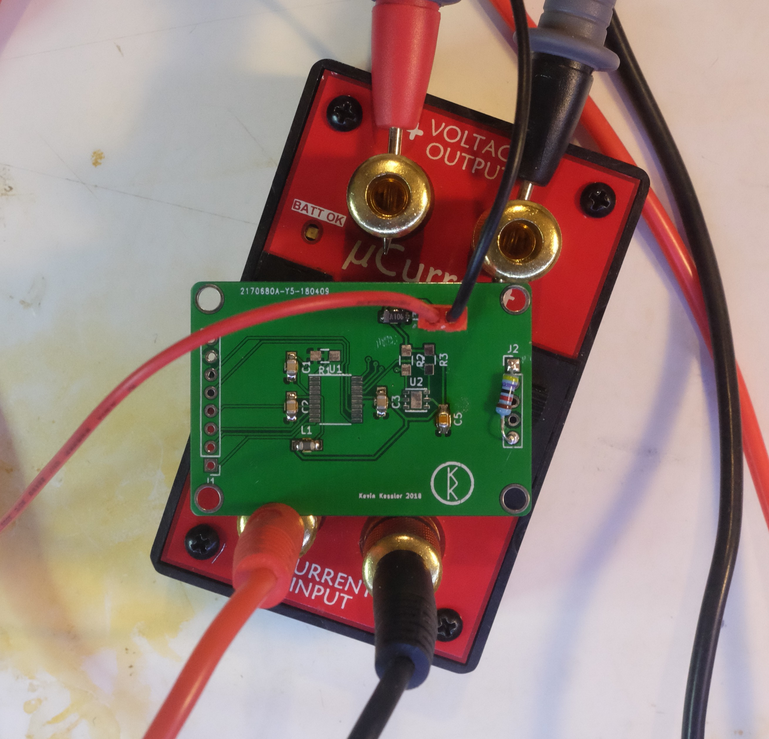
The resistor is between Vdd and the NRST pin, and models the internal pull up resistor on the reset pin of the STM32L0, to which a 100nF cap is connected.
The result? The leakage current was immeasurably small (less than a nA), which was somewhat disappointing. The capacitor beside the power connector is a 10uF Tantalum, and I had bought some 10uF MLCC caps to compare the leakage between the two types of caps. I figure there are 3 possible reasons for this. Jack Ganssle had overstated the importance of capacitor leakage, my uCurrent was not measuring low currents well, or I am some sort of savant when it comes to designing low powered PCBs. While I favor the latter answer, I did have an issue with my uCurrent's uA range, where the shunt resistor was about 1.5K instead of the 10 ohms it was supposed to be. I just slapped in a new resistor and fixed it, but I thought I should verify the nA range as well. The shunt in that range measured the 10k Ohm it was supposed to be, but I built 100M resistor out of some 20M I had, put 1 volt across it, and the uCurrent read 9.6mV, which corresponds to 9.6nA, and is close enough to 10nA for this work. To give credit where it is due, my Siglent SDM3055 was also able to measure that current at between 9 and 10nA, but I'm still not real pleased with that meter because it takes so long to start up.
I guess I'm that good at PCB design.
Discussions
Become a Hackaday.io Member
Create an account to leave a comment. Already have an account? Log In.