 Kevin Kessler
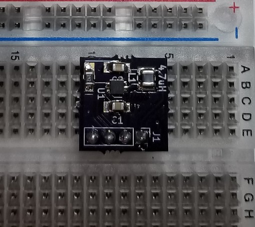
I found an excellent 3.3V boost converter, the TPS61261, which I thought would be able to boost the output of the coin cell to a level that would make the 2 Color Display happy. I had some breakout boards made for it, plugged it into my breadboard, and the display worked perfectly, down to 2V. It did take about 25% more energy than running the display without the converter, but that seemed like a reasonable engineering compromise to make since the current usage of the 2 color display is so small compared to the 3 color display. It also allowed me to turn off the power to the display when in sleep mode, and I measured the current of the boost converter when it was off at 35nA, which I was very happy with.
As I was experimenting with the converter, though, I found out that my problem I was having with the 2 Color display wasn't a voltage problem at all, but it was a problem with using the open drain of the GPIO to switch the ground to power off the display. Basically, the resistance of the internal FET in the STM32 was high enough that a substantial voltage drop appeared between the drain and source of the output FET. The current draw behavior between the 2 and 3 color displays is different enough that the 2 color display just couldn't handle the Vds drop that the 3 color display could. I documented the results in an EEVBlog Forum post where I asked for help understanding this behavior. Using an external discrete switching FET, a IRLML6344, allows the 2 color display to run down to 2 V.
It's kind of too bad I didn't need the TPS61261. I really liked that chip, and I have to find a use for it someday.
I also found in an Arduino library, GxEPD, a different Look Up Table for a full update than the one supplied by the Waveshare libraries. When I tried that, my energy usage for an update dropped from 8.75 mASeconds to 6.3mAS, which would have made up for the boost converter, had I needed it, so now it is just gravy.
So now it is back to China for some new PCBs with a discrete switching transistor. When I get them, I'll do some final current tests, make some predictions as to how long the device will operate on a coin cell, and put in a fresh coin cell and see how close my predictions are.
Discussions
Become a Hackaday.io Member
Create an account to leave a comment. Already have an account? Log In.