 c.Invent
No, the FunKey Zero is not YARPBRGC (Yet Another Raspberry Pi-Based Retro Gaming Console, sorry Eben ;-))!
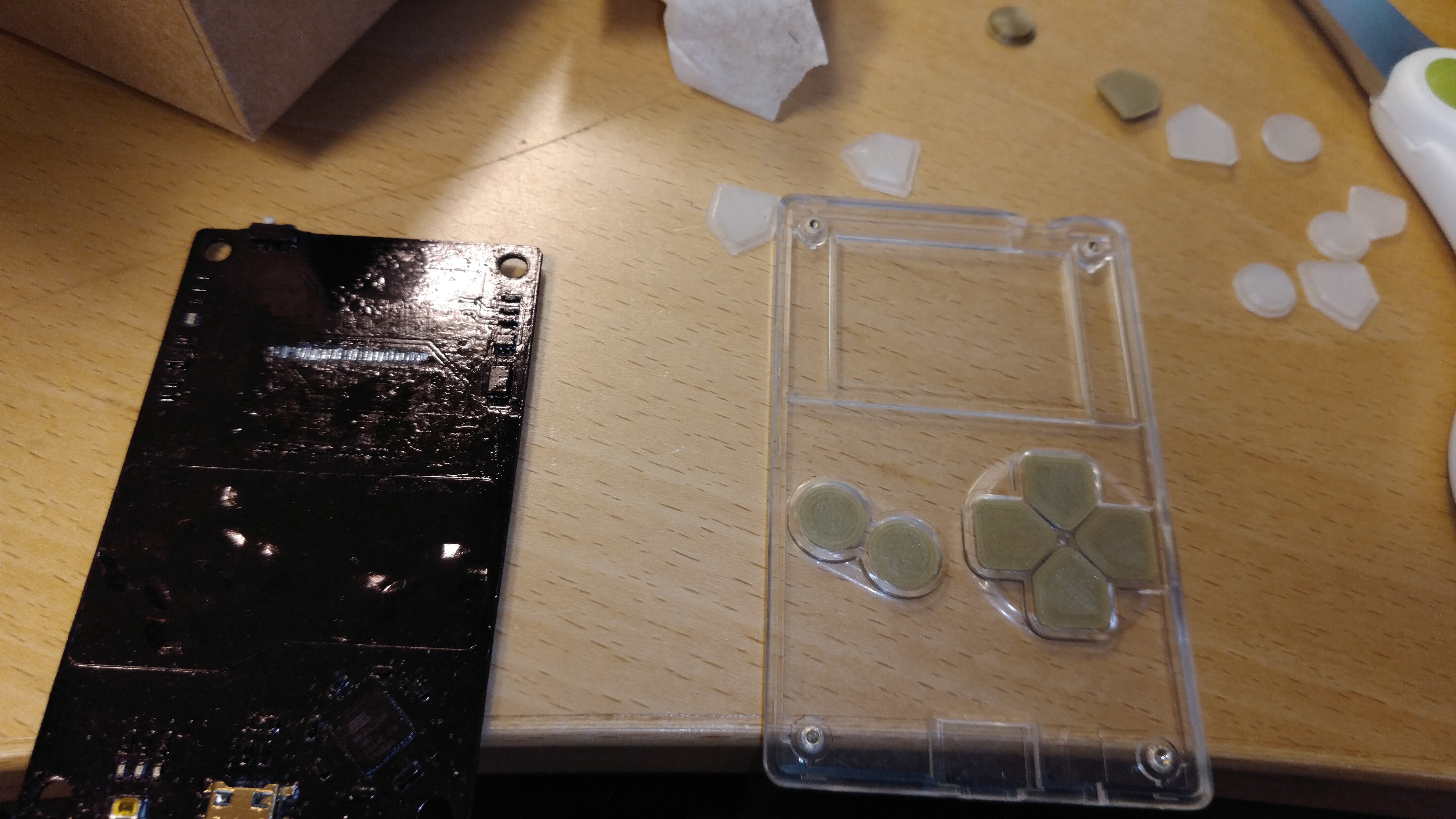
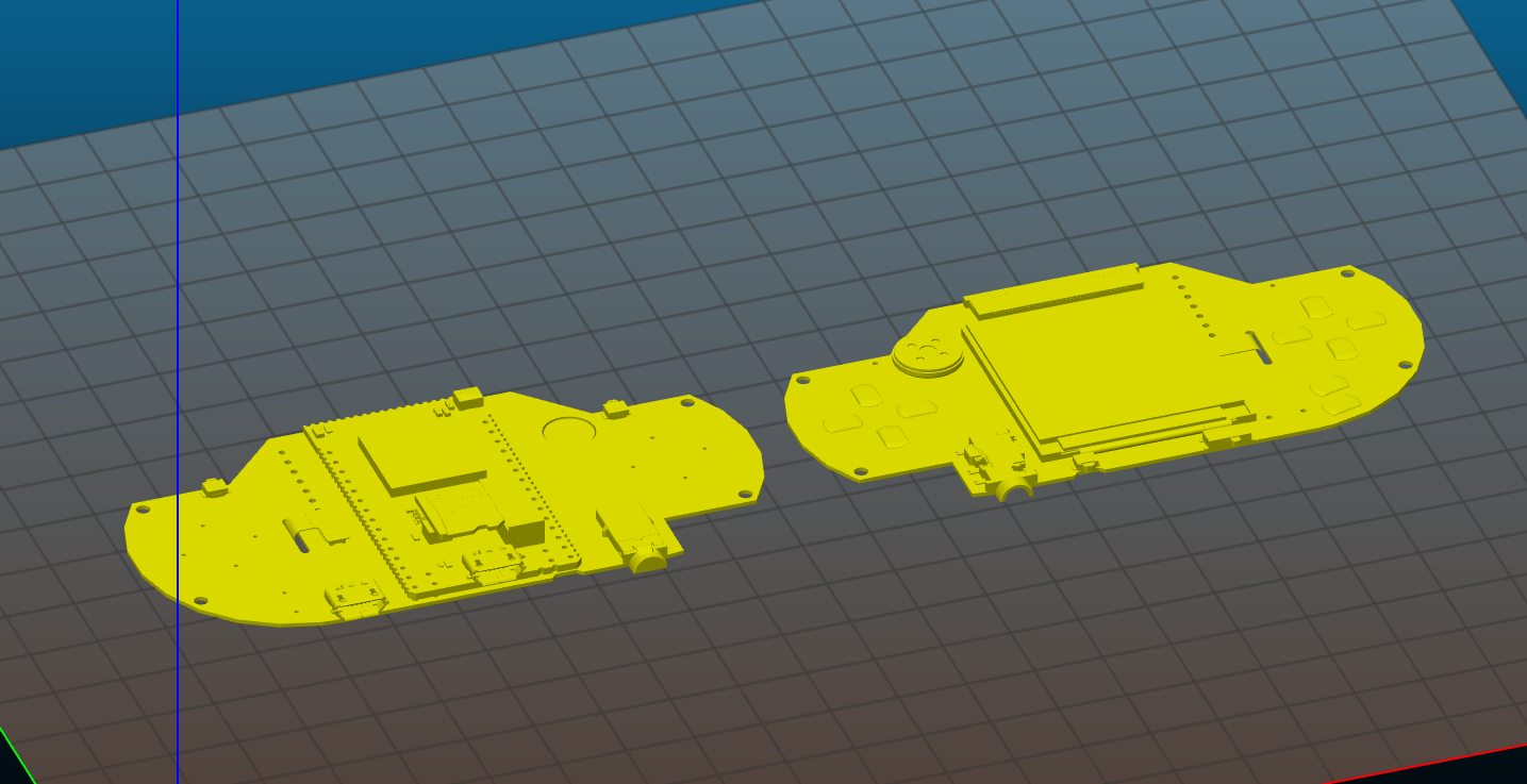
Actually, it must be considered as an original “concept toy” for our tiny (42x46x17mm) #Keymu - open source keychain-sized gaming console .
Unfortunately, the Keymu design was based on the Intel Edison module, which has been retired abruptly with a very short notice by Intel during last September :-(
This situation led us to quickly find the best replacement core that fits into this tiny form factor. But with these stringent overall dimensions, even the Rpi Zero is too large!
And as unfortunately it is not possible to buy the bare Broadcom BCM2835 chip to put it on a smaller custom board, we had to find another candidate CPU that provides a similar very small footprint.
We tried to focus a SoC with integrated DRAM like in the BCM2835 where it is integrated as a PoP (Package on Package) device, as this saves a lot of real estate on the board, and in the meantime simplifies greatly the board layout and PCB requirements.
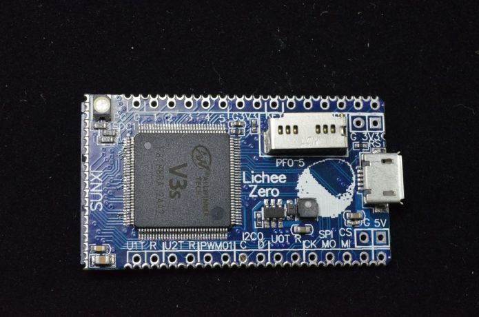
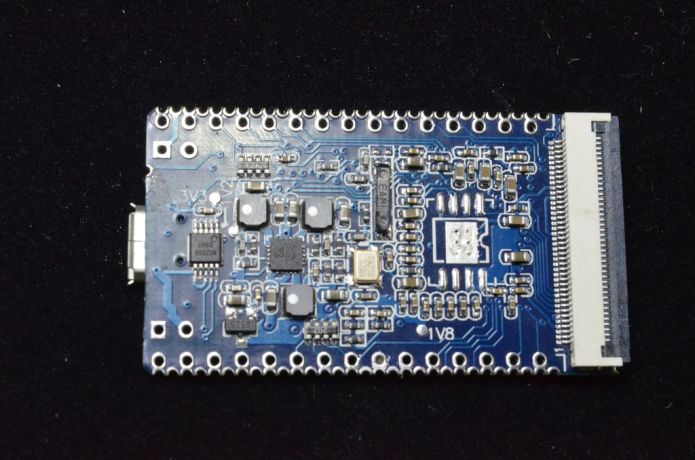
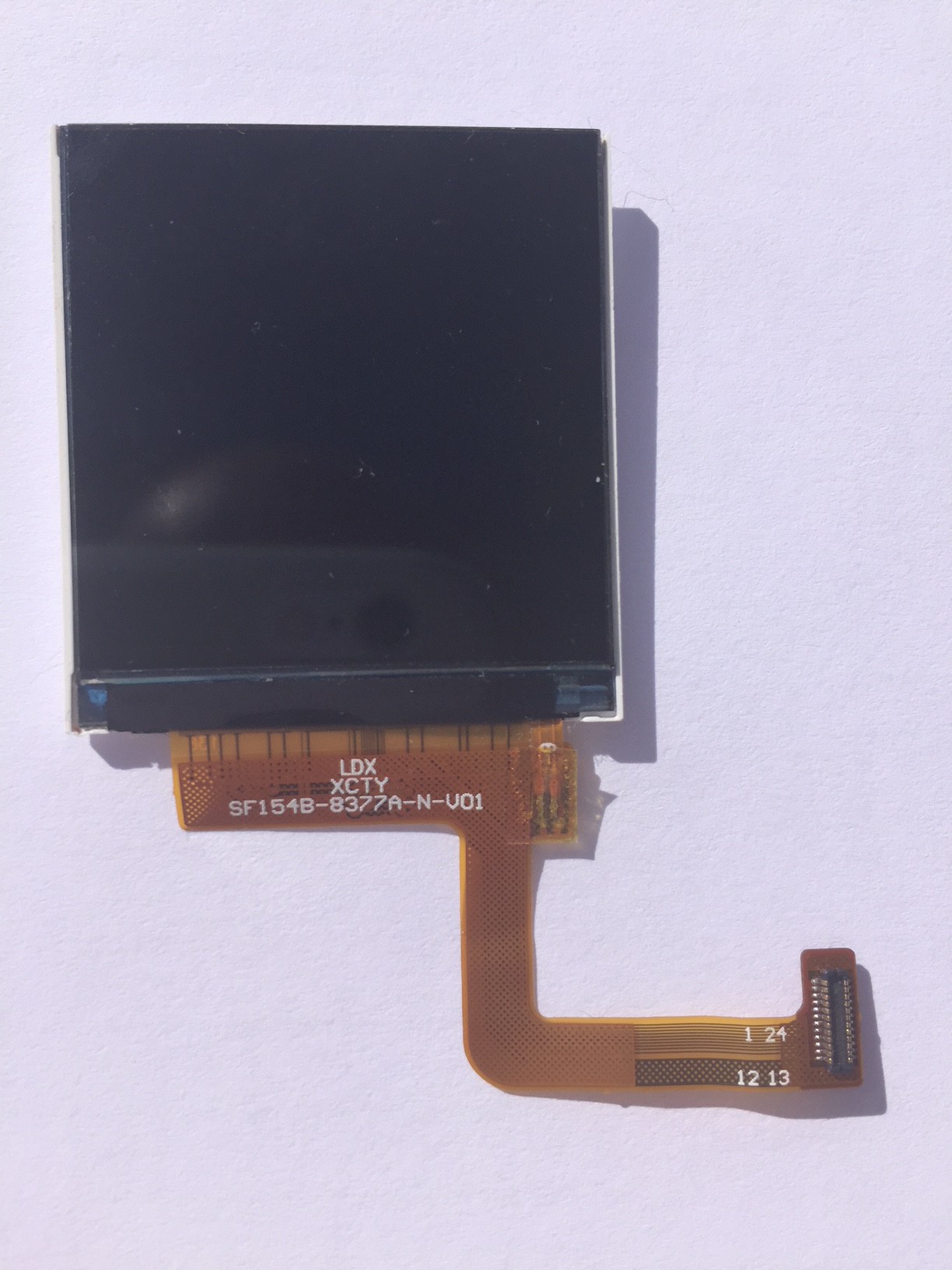
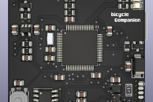
We found only a single serious candidate fitting these specifications: the AllWinner V3s chip, which is a single core ARM Cortex A7 1.2GHz with FPU, NEON SIMD acceleration and with 64MByte of integrated DDR2 RAM. This may not sound much, but we determined that this processing power and RAM capacity is just enough to run our intended retro game emulators at full speed on our tiny 240x240 pixel screen.
So we decided to design a new version of the keymu project with a custom board based on the AllWinner V3s, using the same external hinged 42x46x17mm form factor.
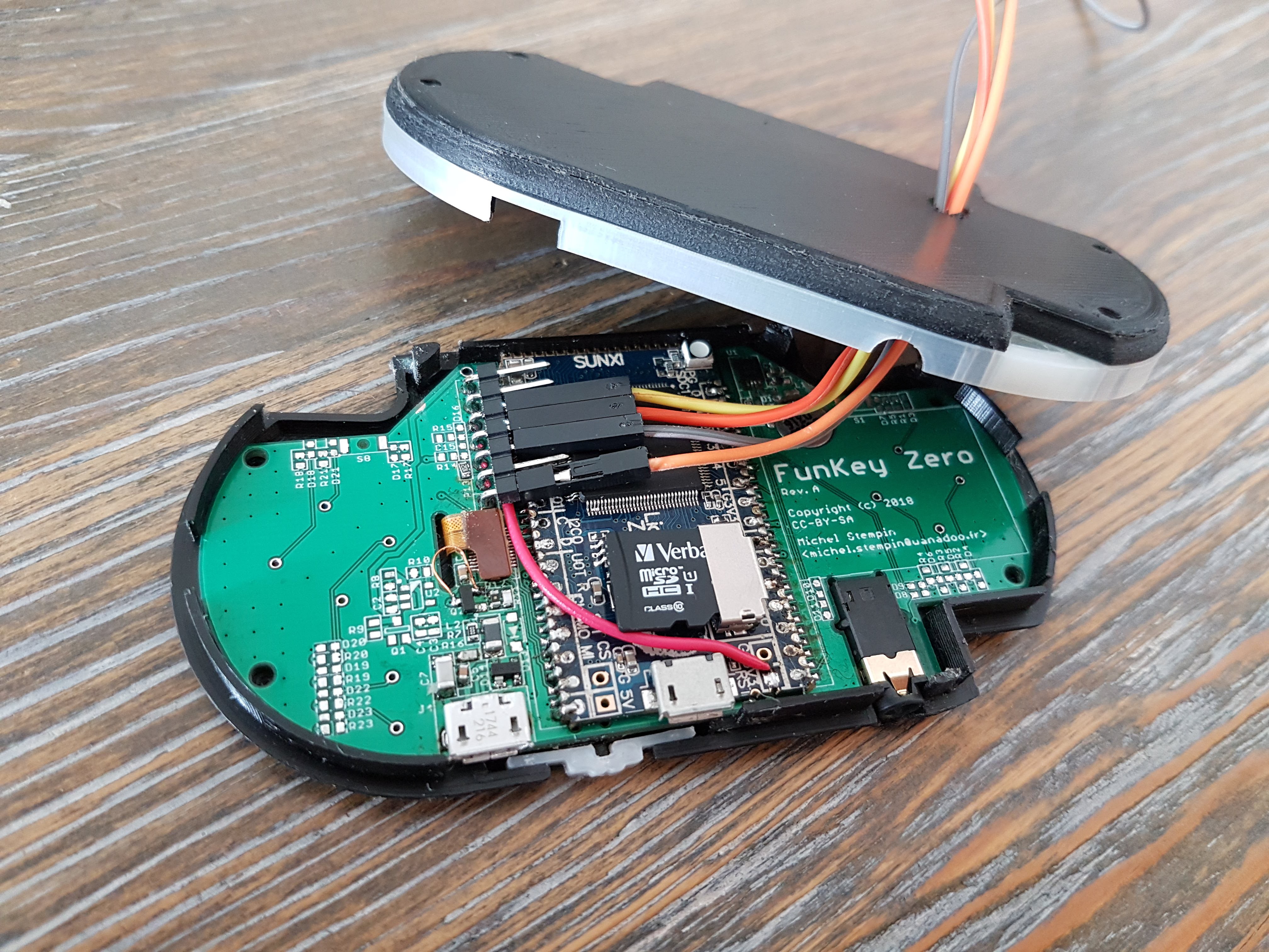
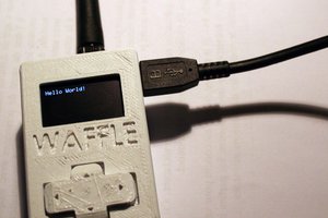
But in order to validate some key design points, we are now building an intermediate non-hinged prototype based on the LicheePi Zero module, which uses the same chip:
https://licheepizero.us/
https://www.indiegogo.com/projects/licheepi-zero-6-extensible-linux-module-on-finger-wifi-diy#/
Here comes the FunKey Zero!
Although this prototype is larger than our target Keymu device, it is still very cool and enables us to test a lot of mechanical, electronic and software features of the final device with only a very small effort.
At the same time, it demonstrates some interesting design tricks that we can and will openly share with our fellow hackers !


 Matias N.
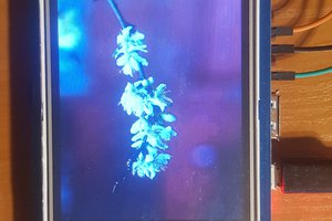
 Marek Więcek
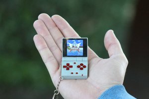
 M.daSilva
too small screen, please look at dingoo console