 Squonk42
U/D/L/R and A/B/X/Y button pads and START/SELECT buttons
One of our most difficult constraint for the #Keymu - open source keychain-sized gaming console is the overall thickness of the device: since it is a clam-shell design where the lid contains the LCD screen, this removes a few mm to the total thickness that must stay < ~15 mm. If you remove from this figure 2x enclosure wall thickness of at least 1 mm, the PCB thickness of 1.2 mm and components height of ~1.5 mm (because of the micro USB connector, mainly) and the battery, this does not leave much room for these button pads.
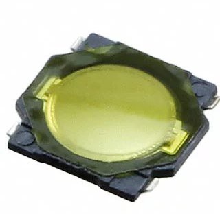
Thus, we started to search for the thinnest button we could get: standard tactile switches are too thick, and the first idea is to reduce the button shaft length, eventually remove it altogether. Performing a search on Digi-Key for tactile switches sorted by actuator height off PCB leads to these 0.35 mm height, 4.10 mm square button:
We thought we had the ultimately thinnest button on Earth, until we discovered the Arduboy tactile dome buttons:
(Check the #Printable buttons for tactile domes project for more details).
The secret is using these tiny metallic pieces that are curved (0.3 mm height for these example ones) and act as springs:
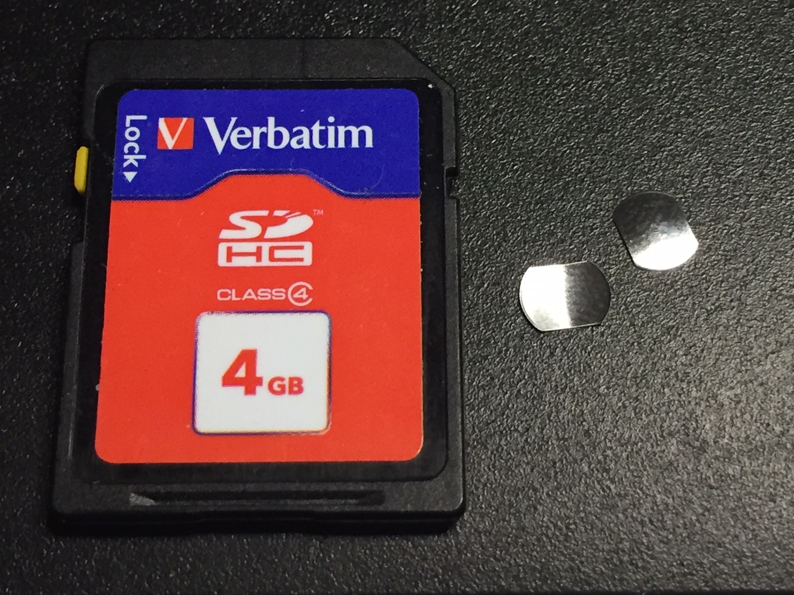
We found these RK22170 models at Snaptron, which were very kind to provide us a free sample kit and a hundred of these (easy to lose) thingies.
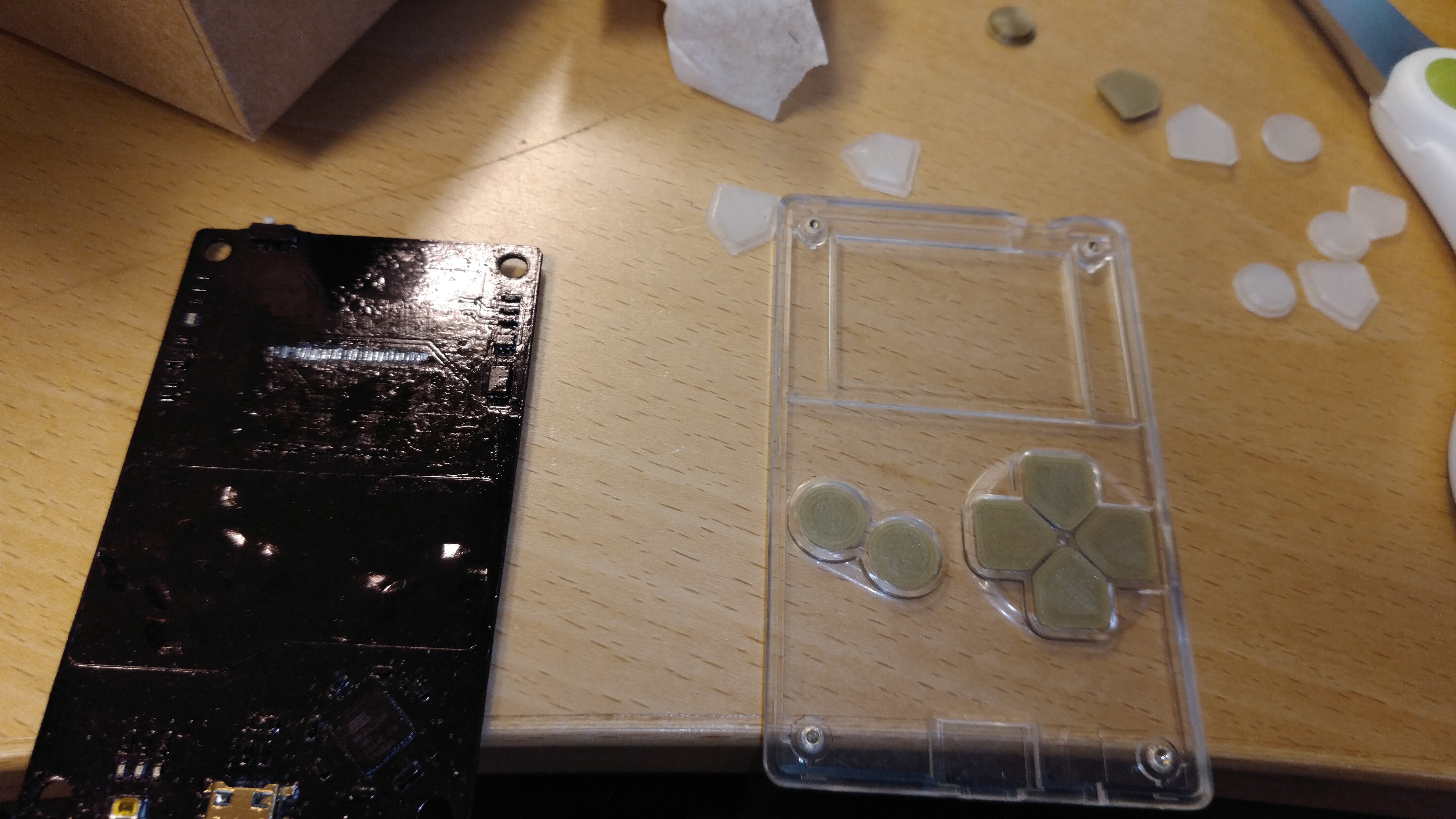
The only PCB footprint you need are 2 bare copper arcs with a central copper circle (no solder mask on all of these!), the dome will make an electric contact between these when pressed. You also need a small ex-centered vent hole to help the air below the button to escape on the bottom side of the PCB, that's all!
In order to keep them in place, you need to stick the domes on a piece of rubber tape, and it is actually not that easy: the required accuracy is rather tight, as the upper plastic button must press right in the middle of the dome, or the button stroke is extremely shorten.
Although we did the PCB with these footprints, we are not sure yet if we will keep these or not, or go back to our previous SMT ones because of this strict alignment problem: SMT assembly seems much easier to perform than glue these jumping domes on a piece of rubber tape.
Rear LEFT/RIGHT and RESET Buttons
For these buttons, we needed the smallest right-angle SMT buttons possible, and we found these B3U-3000P(M)-B models from Omron (3 mm x 2.5 mm x 1.2 mm, without shaft) :
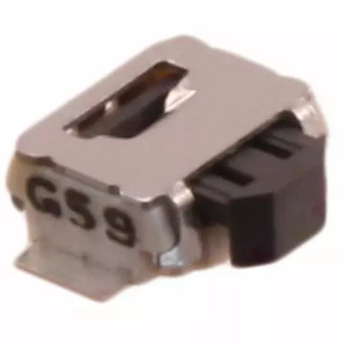
We choose the model with a boss and made a footprint with a hole in the PCB in order to have a mechanical pin that would make this SMT button resist large forces that could tear it off the PCB.
For the RESET button, it is mounted recessed on the PCB and will require a small paper clip to be inserted in a hole on the enclosure to activate it.
As for the rear LEFT and RIGHT buttons, we designed a 3D printed piece with a flexible axis between the 2 large external plastic buttons that presses on the actual button shaft with some very nice elasticity. We were a little bit skeptical about this solution when we designed it, but it proves to be quite nice, the haptic characteristics are very good!
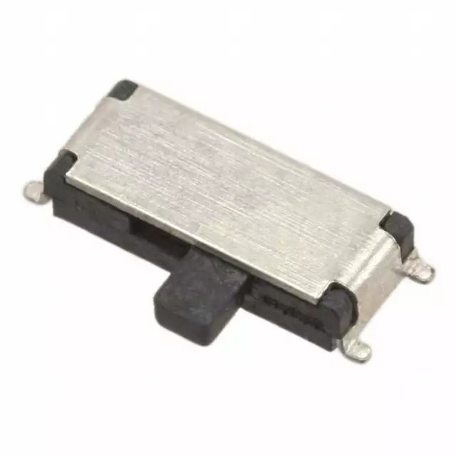
ON/OFF Slider
We wanted to have a real ON/OFF slider, but as usual, we needed it to be as small as possible!
However, as this is a power switch, it had to withstand the maximum current that the device could draw, ~200 mA.
We found this small PCM12SMTR slider switch that can handle 300 mA which is only 6.7 mm x 2.6 mm x 1.4 mm, without the knob:
ESD Protections
As discussed in our previous log, it is very important to protect all user-accessible buttons and keys from ESD by adding a TVS diode as close as possible to the button pins, with a short path to a good ground plane in order to shunt the ESD energy to ground as much as possible, thus protected all subsequent devices connected to the button.
For this purpose, we used some tiny 0402 bidirectional TVS diodes mounted as close as possible to the buttons (oops, well, we did not put one on the ON/OFF slider switch, just forgot it!).
Pull-up Resistors
We also provisioned a 0603 resistor footprint near all the U/L/D/R, A/B/X/Y, rear LEFT/RIGHT and START/SELECT buttons to mount pull-up resistors. This should not be necessary as the Allwinner V3s already has internal pull-up resistors, but this may be nice to have in case e cannot active them for some reason in the Linux Device Tree description.
Discussions
Become a Hackaday.io Member
Create an account to leave a comment. Already have an account? Log In.
I know I'm posting 2 years after the fact, but I'm wondering what the "rubber tape" is - I can only find 2 sided tape or electrical tape when searching, but I'm pretty sure you aren't using either of those two things.
Are you sure? yes | no
Hi Jonathan, I think the "rubber" in rubber tape was misleading. We simply meant a standard thin one-sided transparent tape. It's the general way to stick snap domes to a PCB: http://www.nicomatic.co.uk/pages/products/metal%20domes/dome%20arrays.htm
Are you sure? yes | no
I get that your design is already mostly done, but in other designs, you can reclaim most of that 1.5mm taken by the USB socket by mounting the socket on the same side of the PCB as the buttons.
Are you sure? yes | no
The problem is that we don't have the real estate on the button side... The Keymu PCB is only 42 mm x 38 (the Funkey is larger, about 90 mm x 65 mm), and the micro USB connector is 7.86 mm x 5.66 mm (huge ;-)), so it is very difficult to place on the top side.
On the Keymu:
https://hackaday.io/project/21453/gallery#8b6296887d578c6d07368d298776186f
And on the FunKey Zero:
https://hackaday.io/project/134065/gallery#f91abc096148a4ab16d4027ab9fbc15a
Are you sure? yes | no
Oh, nice, you have a sunken USB socket!
Are you sure? yes | no
A charging station is always an option, if everything else fails. Then you can have a custom connector as small and flat as you need. Custom cable is also possible — I think the iPod Nano does USB over the audio jack connector.
Are you sure? yes | no
I can no longer reply to you because the thread is getting too deep!
We plan to use the USB for both charging the battery and for providing an USB mass storage device to a host PC in order to transfer ROMs, for example, as we don't have Wi-Fi nor Bluetooth onboard.
Are you sure? yes | no
That's a very convenient approach. But since you usually only charge/upload at home, a special cable or a docking station with the correct socket could be a good compromise. Many smartwatches do that.
Are you sure? yes | no