 Squonk42
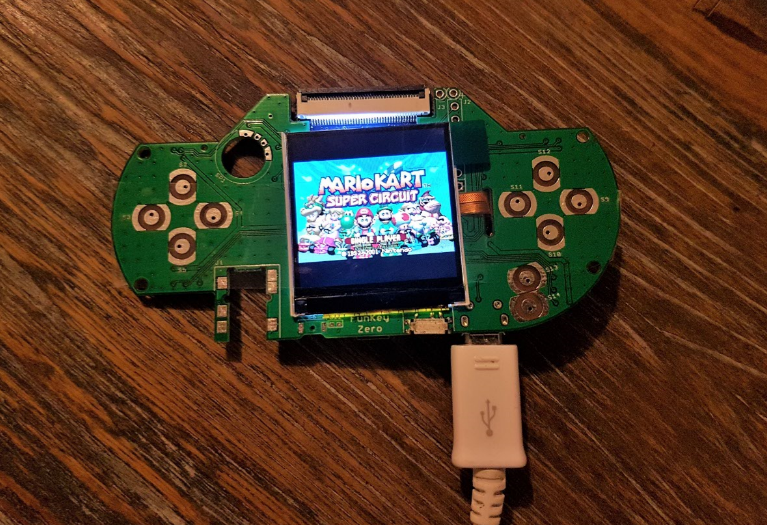
We got a design bug on the LCD PWM MOSFET: the LEDA signal was driven by the N-MOSFET source instead of sinking by tits drain. We had to cut 2 traces and the problem was fixed, the backlight started to work.
But there is another problem with the LCD RESET signal, looks like it is not always pulled to VCC as it should. We may have to unsheathe the scope to debug.
But at least, the LCD is working, as you can see!
Discussions
Become a Hackaday.io Member
Create an account to leave a comment. Already have an account? Log In.
Sorry, the picture is not clear: the top right corner tab is not a connector, it is just the screen protection that can be peeled off.
The screen flat ribbon cable has a rather strange shape, and we must fold it twice and insert it into the slot, the mating connector is soldered on the bottom of the PCB.
Are you sure? yes | no
[btw you need to hit the reply button]
I think @deshipu is talking about the connector above the display, the white one with a lot of pins
Are you sure? yes | no
OK, I hate the HaD stylesheet ;-)
The top white connector is the one that is part of the LicheePi Zero board itself.
We don't use it here, as it is RGB interface only, and our nice little 1.5" 240x240 pixel LCD screen uses an SPI interface.
But it may be used to drive a larger RGB screen, of course.
Are you sure? yes | no
I see, I suspected this, but I didn't see that connector on the other photos of the licheepi, so I got confused. Thanks for clarification.
Are you sure? yes | no
Are there two connectors for the screen? I assume the narrow one on the side is what's important, because the chip is at the bottom. What is the top connector for?
Are you sure? yes | no