 Squonk42
Like described in the project details, we decided to use the LicheePi Zero module as the core of our FunKey Zero device. As explained, this module features an AllWinner V3s SoC, which has just the right capacity for our purpose, and a minimum size because of its integrated DDR2 RAM:
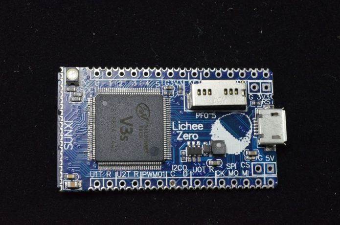
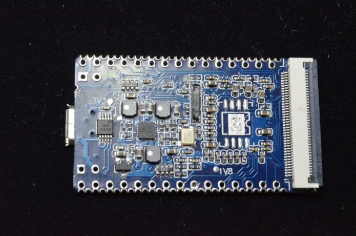
With a size of 44.65 mm x 25.53 mm x 8.00 mm, it is small enough for the FunKey Zero, but not for our final keymu device. It features a low power consumption and all the required peripheral that we need.
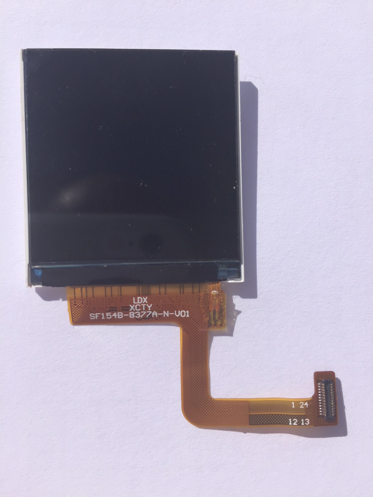
Another very important part in our design is our small 1.5" LCD screen. It has an amazing 240 x 240 pixel resolution, while using a simple SPI-based interface and not a complex DSi interface based on the differential high-speed MIPI specification, which requires a dedicated controller that is only available in higher-end SoC:
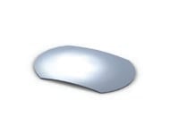
For audio playback, we wanted to have an internal speaker. But given the reduced dimensions, we tried to find the smallest available one, which has a very small 10 mm diameter, with a total height of 2.9 mm, out of which 1.4 mm can be inserted into a PCB hole, thus only having a height above PCB of 1.5 mm:

We use a simple mono audio playback through a MAX97000DETB+ amplifier. This amp has all the required characteristics, but uses a non user-friendly DFN10 package, so we designed a special footprint with long pads to make it easier to solder.
We also provided an external audio headphone connection using a standard TRRS 3.5 mm audio jack. We chose a mid-mount model, i.e. one which requires a cutout in the PCB. This way, we can "mask" its height into the PCB thickness, leaving only a 1.5 mm height below and above the 1.2 mm thick PCB:

To keep the design as thin as possible, we found the best solution was not to use standard tactile switches, but to use tactile domes instead: with dimenions of 5.59mm x 4.19mm and a height of only 0.3mm, they only requires a copper area on the PCB and costs nothing:
We also need some right-angled tactile switches for the rear left and right button, as well as for the recessed RESET button:

We took the smallest we could get, but we may experiment with softer (no-click) ones for the rear buttons to bring a better play experience.
We needed an ultra-small slide switch for the on/off function, here is the one we found, only 7.7mm x 3.5mm x 1.4mm, not counting the knob itself:

We had to add a separate microUSB connector instead of using the LicheePi Zero built-in one, as we need to get access to its +5V pin in order to feed a LiPo battery charger circuit. We choose a common model with through-hole pins in order to avoid tearing it off the board if you don't pull the chord straight.
The LiPo battery charger chip is a standard MCP73812T-420I/OT, followed by an ideal diode made up of a P-MOSFET and a Schottky diode, like originally used in the OLIMEXINO-32U4 board. The ideal diode will allow charging the LiPo battery while the USB is connected by disconnecting the battery from the load, and reconnect it to the load when the USB chord is not connected. Clever, isn't it?
The only remaining mechanical part is the small DF37NB-24DS-0.4V(51) connector, matching the LCD screen connector. It is a very fragile part that does not withstand too much heat from the soldering iron, so we designed a special footprint with as long as possible pads in order to solder it using the capillarity effect as much as possible.
For debug, we features a 7-pin right-angle 2.54mm pitch header, compatible with standard FTDI cables while bringing some extra signals on non-essential pins and adding on extra pin.
The only remaining active part is an N-MOSFET used to drive the screen backlight from a V3s GPIO pin.
We made provision for TVS diodes on all user-accessible parts to prevent ESD, these are small 0402 TVS that can be optionally mounted, and a dedicated USB ESD protection a close as possible to the USB connector.
All other parts are passive resistors, capacitors or ferrite beads in 0603 form factor, as we have a lot of available real estate on this board.
As you can see, none of the component was chosen randomly, and finding the right part took us a significant amount of time!
Discussions
Become a Hackaday.io Member
Create an account to leave a comment. Already have an account? Log In.
I wonder what SPI clock frequency does that display support? You don't have problems with slow updates?
Are you sure? yes | no
In truth we have to say that this screen exeeded our expectations.
The screen is based on the ST7789V driver which specifies a 66ns maximum write cycle. This corresponds to a theoritical minimum of approximately 15MBits per second. In practice we have tried higher clock frequencies and the screen supports up to 80MBits/sec (the V3S is capable of 100MBits/secs) !
We finally settled on a 40MBits/sec frequency, allowing us to boost up the fps to 42 frames per seconds while keeping the CPU load dedicated to fbtft to an acceptable value (around 1-2% for all non DMA handled exchanges).
Are you sure? yes | no
Wow, that is very nice indeed! I have a breakout board for that display waiting in the queue for me to write a driver for it, I will need to look into it sooner.
Are you sure? yes | no