 Squonk42
Apart from the core itself, the next important decision is the the choice for the LCD screen.
Dimensions
As stated earlier when we discussed about the core, the whole point for the FunKey Zero project was to prototype as much features as possible for the #Keymu - open source keychain-sized gaming console device.
We determined that the maximum dimensions should not exceed ~ 40 mm x 40 mm x 15 mm, or we should not call it a keychain emulator anymore ;-)
For the Keymu, we considered that the screen should be as large as possible and adopted a "clam shell" form factor to protect the fragile screen and buttons from impacts on the keychain.
But these decisions seriously restrict the available screen size: if you consider that the screen can fill the whole 40 mm x 40 mm surface, the maximum possible standard screen size that works is then 1.5" or 38.1 mm in diagonal, or 26.94 mm square.
Screen Interface
First of all, the picture to be displayed must be buffered ("frame buffer") on one side, either on the CPU side, or in the screen module itself, which leads to 2 different screen module types:
- in the first case, the screen module does not contain any RAM and is just a "dumb" display that needs to be constantly refreshed in order to display a picture, using pixel clock, horizontal and vertical sync signals, and of course, the pixel data, usually in an RGB666 (18 data bits from D0 to D17) or RGB888 (24 data bits from D0 to D23), plus a few additional signals. These screens are mostly used to display "live video" coming from a camera sensor like in Handycams or dashboard cams
- in the second case, the screen module contains a memory, often called Graphic RAM (GRAM) that does not need constant refreshing in order to display a picture. This type of screen is generally used for static displays like UI with buttons, check boxes and sliders
In the case of "dumb" screen module, the screen interface is generally called "RGB", with a variant "RGB8" where each color component is transferred one after the other (each pixel needs 3 transfers).
For the screen module featuring internal GRAM on the other hand, there are several standard interfaces used to drive them:
- for the smallest screens, an I2C bus is used. As these screen do not contain many pixels, the I2C bus with its maximum speed of 400 Kb/s is more than enough to drive these, and it only requires 4 wires: VCC, GND, SDA (Serial DAta) and SCL (Serial CLock). At 25 fps and 65536 colors, the maximum resolution you can expect is thus... 32 x 32 pixels!
- for screens with more pixels, the I2C bus just is too slow to allow high fps numbers, and an SPI bus is used instead, which requires a few additional wires, usually: VCC, GND, SDI (Serial Data In or MOSI), SCLK (Serial CLocK), CS (Chip Select), RS (Register Select), RESET and most of the time a separate power supply for the LED backlight. Speed is often specified up to 8 or 10 MHz, and at 25 fps and 65536 colors, the maximum expected resolution is 128 x 128 pixels. But it is not uncommon to have integrated screen controllers going up to 40 or 50 MHz and in this case, the resolution can go up to 240 x 240 pixels with the same picture parameters!
- in order to reduce the required interface speed, some screen modules use parallel buses with 8, 9 , 15, 16 or 18 bit bus, dubbed "MCU", "MPU", "Intel", "8080" or "6800"
- for the screens with the highest resolutions (including the ones used in smartphones and tablets), the interface used is a high speed differential serial, user-unfriendly interface called MIPI DSI (Display Serial Interface) requiring a specific controller, only available in high-end mobile phone CPUs
Clearly in our case, solution #1 is not possible, as well as solution #4, as we don't have the corresponding DSI interface in our CPU. This leaves us with solution #2 or #3 or a dumb screen with RGB or RGB8 interface.
Hinge
Because of the constrained dimensions, we want to use a "clam-shell" design, like the cell phones from some years ago. This implies a hinge between the screen and the main enclosure body, into which the screen module flat cable must go into.
But in order to remove some mechanical stress from this flat cable, the flat cable should not go straight through the hinge or chances are that it will break very quickly after several lid open/close sessions.
The solution is to roll the screen flat cable into the hinge internal cavity much like a sticky fly ribbon.
This means that the screen module flat cable should be as long and as narrow as possible, which is only possible for solution #2 above, i.e. using an SPI bus.
Screen Resolution
Given the constraint of a 1.5" screen size and an SPI interface with a long flat cable, a quick search on AliExpress / AliBaba provides a long list of similar screens, which resolution does not exceed 128 x 128 pixels: we used one of these in our Edison-based Keymu device.
But based on our previous experience, we knew that this resolution is not sufficient to play retro games featuring small fonts, even when using anti-aliasing.
So we kept searching and we got excited several times when finding 1.5" screens with a 320 x 320 pixel resolution, but every one of them turned to use an impossible MIPI CSI interface :-(
This was until we found this 1.5" screen using an SPI interface and with a 240 x 240 pixel resolution:
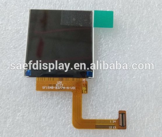
OK, well, the ribbon cable may not be long enough to be rolled into the hinge... But this is something the manufacturer can customize for a fixed tooling fee of $800...
And despite what is specified in its ST7789V controller chip datasheet, its SPI write clock cycle can be much shorter than Twc= 66 ns (15.15 MHz) and can go actually up to ~60 MHz!
We asked the manufacturer about this performance and they confirmed the achievable speed, as well as the ability to use a +3.3V voltage for the backlight LEDs instead of the specified +2.9V. BTW, this is another positive point for this screen: the backlight LEDs are wired in parallel and not in series. This raises the current requirement, but also lower the LEDA/LEDK voltage and removes the need for an additional step-up voltage converter just for this purpose.
And now the cherry on the cake: this screen has both a wide angle of vision of 80° and a contrast of 400:1 thanks to its IPS technology!
Last but not least, the ST7789V is also readily supported in the stock Linux kernel fbtft driver to provide a frame buffer over the SPI bus.
A breakout board for an equivalent screen (not same pinout and connector) featuring the same ST7789V controller chip is available at Adafruit.
Discussions
Become a Hackaday.io Member
Create an account to leave a comment. Already have an account? Log In.