 Yann Guidon / YGDES
Having a Cray-1 type board and some documentation about it, it only came recently to my knowedge that it is mostly made of (N)OR3 ECL gates. What I didn't realise is that it's not comparable to, say, a 74F00.
First, larger logic fanout : 3 inputs, instead of 2. (edit : better ! OR/NOR4 and OR/NOR5 ! please disregard the mistake in the rest of the text) It changes everything. Two dual NOR3 in ECL can do the same as 4 NAND2 in TTL, in the same package size. You can easily make a latch with bells and whistles, and less critical datapath than, say, what #NEDONAND homebrew computer can do...
Second, you got complementary outputs. You can use the inverting or non-inverting output, or both. With NAND2 (74F00) you must waste another gate to invert it, and even risk adding jitter/glitches...
This is another killer characteristic. OK ECL consumes more, and uses more transistors but it's not only faster, but uses less gates overall. So it now makes sense to me that Seymour Cray chose this, and trying to design a circuit with it shows that it's actually very sound.
I have been wondering today how to design a 2^N multiplexer. This is simply a circuit that selects from one input out of 2^N. Nothing fancy but since there are alternate ways to design an ECL latch, I wondered if there was an ECL MUX2 topology. ECL does not allow a signal path to cross the gate directly so it must be "computed" by transistors. X = (A & S) | (B & /S)
The transistor topology does not look good because the AND parts require two transistors in series. This is electrically more complex than the canonical NOR gate.
Now what happens in NOR3 world ? A MUX4 would be originally written as
X = (A & S1 & S2) | (B & /S1 & S2) | (C & S1 & /S2) | (D & /S1 & /S2)
OK let's say that we have a (N)OR4 for the main output. The 4 inputs are fed by ANDs. But wait,
X = A & B = /( /A | /B)
So the ANDs can be transformed into ORs with more bubbles. And now comes the bubbles-pushing games !
The ANDs will use the complementary output of the NOR3 gates, so this comes "for free". The AND's input bubble will come from the latch's complementary output. And S1 and S2 will use both complementary outputs. The MUX uses no inverter anywhere, and only 2 levels of logic gates !
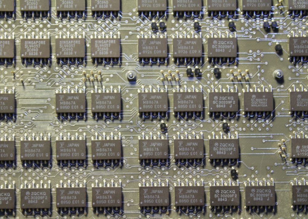
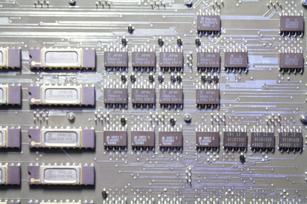
Close view of a Cray-1 IO board. Fairchild and Motorola ECL chips, the tiny black dots are 2-resistors divider networks for termination. CRI chips too...
What's the pinout of the 16-pins small gates ? I can't make sense of it, 3 inputs + 2 outputs = 5 pins, add 2 for GND and Vcc. 2 NOR gates => 12 pins, 3 NOR gates => 17 pins. This does not match. Help.
Drive strength is another convincing factor (for Seymour Cray at least). For long distance communication, just use the pair of complementary outputs and send them over a twisted pair. Add some termination at the receiving end and use the signal(s) you need.
ECL gates are pretty sensitive and have low swing (the lower, the faster, and Germanium has a low threshold voltage). This helps with fanout, if the buffer transistor's gain is high enough. I wonder how many gates can be driven by my germanium transistors, the AF240 has a quite low hFE...
Fanout is to be determined.
Looking at Dieters's MT15, I think about @roelh's ALU with this picture:

My brain did not "see" the propagate/generate units but the couple of MUX4 of the ALU. But I realise now that MUX4 trick might be the best idea so far, and it would save a XOR layer for one operand... And I've found that MUX4 totally ECL-friendly :-)
The big problem now is to deal with all the fanout and control signals. Dieter had a LOT of troubles with that...
Discussions
Become a Hackaday.io Member
Create an account to leave a comment. Already have an account? Log In.
I was looking though some logs related to the Cray-1. Those chips contain 2 gates. There's a 4-input and 5-input gate with complementary outputs (13 pins) plus Vcc1, Vcc2, and Vee to make 16 pins. The original Cray-1 used the Fairchild 11c01. I have a logic board out of a Cray-1S and those are Motorola parts (can't find a data sheet on them). The Fairchild chip is online - https://www.digchip.com/datasheets/parts/datasheet/161/11C01-pdf.php
Are you sure? yes | no
Thanks !!!
Are you sure? yes | no