 Yann Guidon / YGDES
I love logs !
I write stuff I think, and when it's over, it makes me think more...
The last log "Register set musings..." now looks somehow ridiculous to me. I blindly applied the approach I used for the relay version (#YGREC16 - YG's 16bits Relay Electric Computer) but the fanout tree becomes incredibly unsustainable. So I went back to the sketchpad and figured another latch topology.
Still 6 transistors at the core, but organised differently, using a single-ended latch signal. This shrinks the driving logic significantly. Actually, the transistor count doesn't change, I have moved a "feature" closer to the latch cell, but I have also moved other things.
I start to play with transistors in series to create AND functions and applied this idea to the output buffer as well : a double wired-OR now replaces the two MUX8 for the read ports. All I have to do now is create three DeMUX8 to drive the respective enabling transistors, and each output of the DeMUX8s have a fixed fanout (16 for 16 bits).
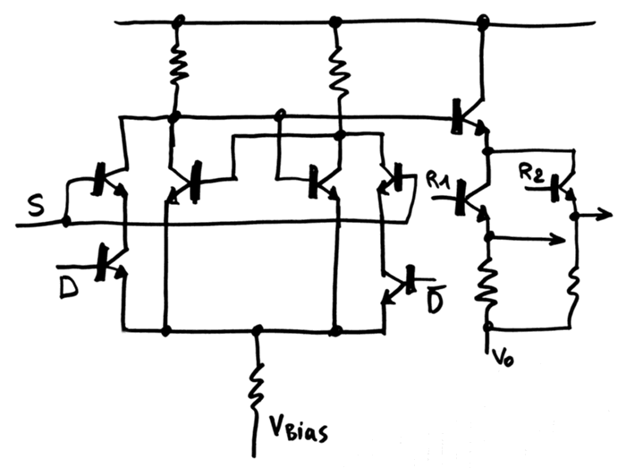
Initially I had put the S (select) transistor at the low-side of the AND string but realised that the fanout would be always 2, since the base current would flow through both sides of the cell.
With the high-side version, the current flows either through the left or the right side because D and /D are mutually exclusive.
I am deliberately choosing asymmetric, non-ECL signals as a compromise between speed and parts count. I know I'll have a few issues with signal levels/swing because the bases will end up at different voltages, but I'm ready to increase the signal swing. I just want to keep the parts count as low as reasonably possible, without using xTL circuits...
20161225: More thinking
I now get "why" the "series" topology is often avoided, at least with bipolar transistors. The base current (the switching control signal) goes to the emitter, and with a hFE of 20, the margin is reduced. The bipolar version with higher gain will probably solve this, thanks to lower control current (better sensitivity) but I have yet to solve the current issues.
For the input ports, D and /D will inject some current (base to emitter) and slightly increase the common floating node's voltage. But since D = / (/D), there is always current (of roughly the same value) going through one of the branches. There shouldn't be much problems (except maybe during state changes) and the common node voltage should remain the same (more or less).
Things get ugly at the output. Base currents everywhere and necessary level shifting... Unless I shift the Vo node down to 0V ?
Discussions
Become a Hackaday.io Member
Create an account to leave a comment. Already have an account? Log In.