The problems address by this update all relate to the Z axis of all of these i3 printers.
Bent Lead screws push the x assembly back and forward. Fix: replace screws with low pitch straight accurately made lead screws.
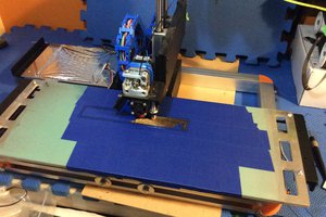
The up and down movement is caused by another problem that has been addressed in various ways by different manufactures. This is caused by the spring movement caused by the coupling between the lead screws and the steppers. When the extruder moves left and right the whole x axis see-saws up and down meaning that the extruded plastic is released at different heights depending on where the extruder is at the time. This becomes more evident in large prints.
One answer to this is to remove the coupling but this will put undue stress onto the frame and stepper bearings and may lead to untimely failure. My answer to this was to make a bracket for the top of the printer that would hold skate bearings (cheap and easy to get, also fit the 8mm lead screws on my printer - a simple adaptor can be used for the 5mm lead screws that are also used on these printers.) These bearings with the addition of a collar on the top of the lead screw and the top of the smooth rod, now take the weight of the whole X and Z axis. This upgrade has removed the gaps that were present in between some of the larger print layers.
The second addition to these bracket has done away with the need for a separate spool holder. The manufacture's spool holder has worked well most of the time but has meant that sometimes some of the spools jam and break the filament during a print. By updating the bracket to allow arms to hold the spool above the printer I have done away with the jamming issue and also made the line of the filament intersect with the extruder at a better angle. This seems to have removed the filament jamming and breaking issues.
When designing the spool holder I designed it to work with the manufacture's pvc pipe that was in the original spool holder. I also was worried about the spools putting pressure onto the printer and bending the frame which would have caused printing issues. I designed the arms to centre the spool over the frame in both the x and y axis so that the weight of the spool was transferred directly down the length of the main frame.
 ken.do
 Mark Rehorst
 Malte Schrader
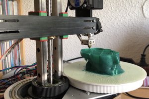
 heinz
heinz