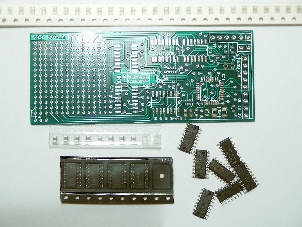
I've got all the necessary parts for the lollipop interface now, so I've gone from this...
to this, with 9V battery for scale:
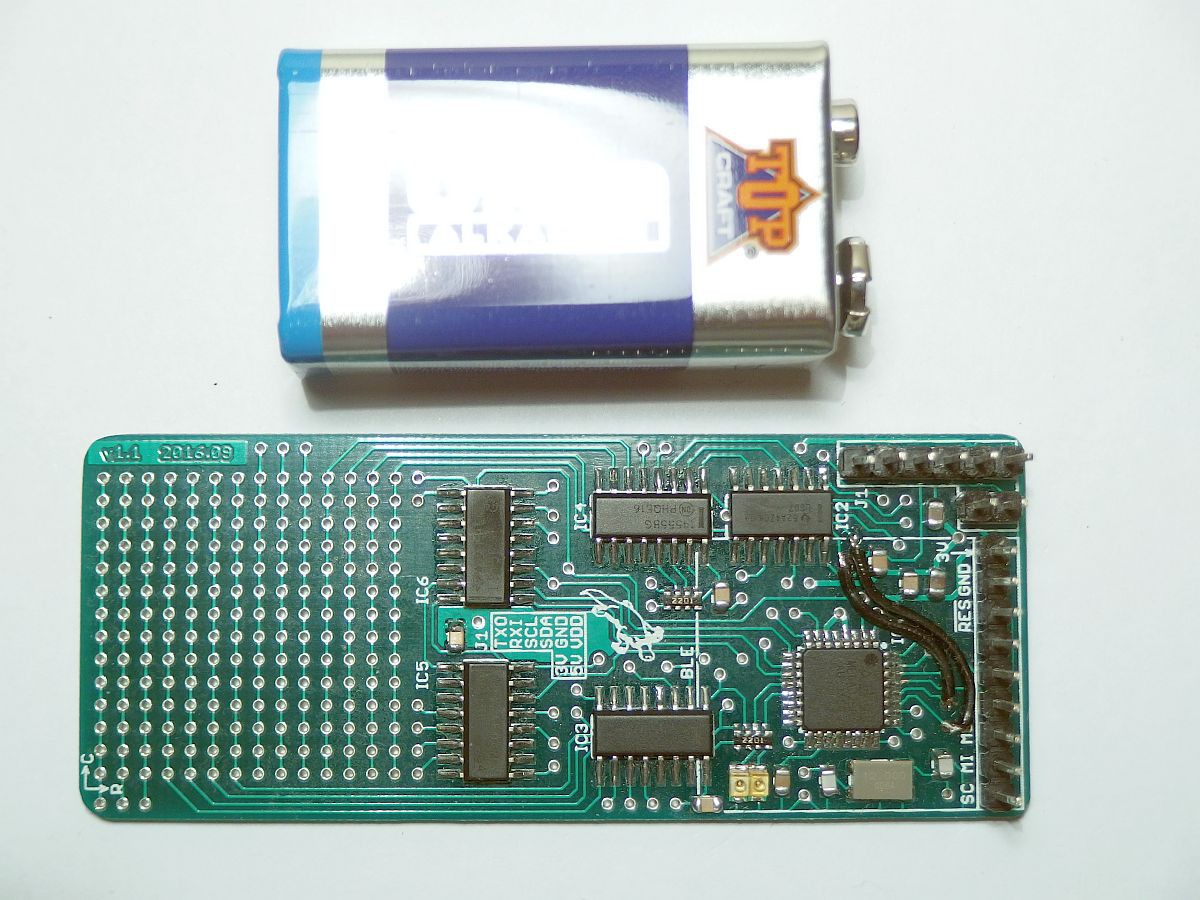
The quality of the boards (made in China) is really nice. I used a conventional soldering iron, as there aren't too many parts, and the sizes are manageable. I used a file to round off the corners of the PCB and get rid of the sharp edges, and cleaned off the solder flux with brake cleaner (not sure what's in this, but it smells like it should be banned).
On the BLE interface connector, the microcontroller MOSI, MISO, SCK and /RESET pins are accessible, and can be used to program it. I programmed a quick bit of code to flash one LED, and it lives! I noticed a mistake I'd made in the circuit - I had thought that port C was a full 8-bit I/O port, but the top two bits can only be used as ADC inputs. This meant that two mux control lines weren't accessible.
Luckily I could connect them to the SDA and SCL lines, which I had reserved for communication with the Raspberry Pi. I hadn't decided whether to use I2C or the UART, so made both SDA/SCL and TX/RX available on the interface pins. The required data transfer rate is rather low, and the UART will suffice, so the SDA/SCL lines can be repurposed as general purpose I/O to control the two missing mux control lines. I added a couple of wires to the top of the board to make the connections and no track cutting was necessary. I've updated the schematic appropriately.
I've also made a connection cable for the Raspberry Pi, that plugs into the GPIO pins 1-10 with a short bit of IDC connector. The cable connects the 5V, 3.3V, ground, TX and RX lines from the Pi to the lollipop interface board. A 9V battery clip provides the power connector for the lollipop 3-18V CMOS supply.
A momentary pushbutton switch provides a means by which to shut down the Pi when running headless. An LED hanging from the 3.3V line is connected to the Pi GPIO4 pin via a resistor, pulling the pin up to 3.3V. The push switch is connected between this pin and ground. When the switch is pressed, it activates the LED, and by pulling the GPIO pin down to ground can also be detected by the software. If necessary, the software could also turn on the LED when the switch is not pressed, by driving the pin low, though I need to avoid driving the pin high to prevent a possible short to ground via the button.

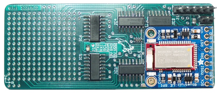
Here's a mockup image of how the lollipop board might look with the BLE interface fitted (not intended for the current prototype, but to be supported in the future):
The next steps are to write the microcontroller software, and then get the Raspberry Pi talking to the lollipop interface via the UART connection.
Discussions
Become a Hackaday.io Member
Create an account to leave a comment. Already have an account? Log In.