To determine a suitable size for the interface lollipop, I made some samples with cardboard. I decided that the part in contact with the tongue needs to be no larger than 40x30mm, to fit comfortably inside the mouth. But for the initial prototype, it will be difficult to include the sense matrix and the required driving electronics in such a small area. By making the board slightly longer, but still 30mm in width, there should be enough space. It will stick out of the mouth, but this will give something to hold on to and won't look too awkward.
I decided to design the driving circuitry for a sense matrix resolution of 16x16 pixels. I'm not sure yet whether this number of pixels will fit into the available area, but this is the goal.
To drive the sense matrix I chose the ATMega328P 8-bit microcontroller, because of its versatility and ease of use. It's available in a TQFP package with 20 I/O pins, plus SPI and UART, and is straightforward to program in assembler or C. It's also widely available at low cost, and can be flashed using a simple parallel cable.
To drive the 16 rows and 16 columns, I will need to multiplex the limited number of I/O lines. I intend to use standard logic parts to do this. For the high side (rows), I will use a CMOS part, MC14555P, a dual 1-of-4 mux. By using two of these ICs, I can use 6 I/O lines of the microcontroller to individually select 1 of 16 rows. I can set the row voltage to anything within the allowed CMOS supply range, ie. from 3 to 18V, simply by varying the supply voltage to the mux ICs.
For the low side (columns), I will use a similar dual 1-of-4 mux, but with open collector outputs. A suitable part is the 74LS156. When an output is high, it will float, rather than being driven to the 5V supply voltage of the 74LS156, so no current will be drawn through the sense matrix. When low, the column will be pulled down to ground and the pixel in the intersecting active row will see a voltage across it.
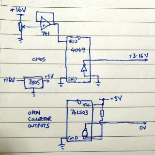
To test out the concept, I built a circuit on breadboard using a high side CMOS part and a low side open-collector 74LS part. The parts used were a 4049 (inverters) and 74LS03 (open-collector NANDs) as I had these to hand. The 74LS was powered by a 7805 regulator, and I used a 741 op amp as a voltage follower to generate a variable supply for the 4049. This let me set the CMOS voltage between 3V and 12V or so when connected to a 16V plug-in supply. I held the high and low output wires against my tongue, about 1mm apart.
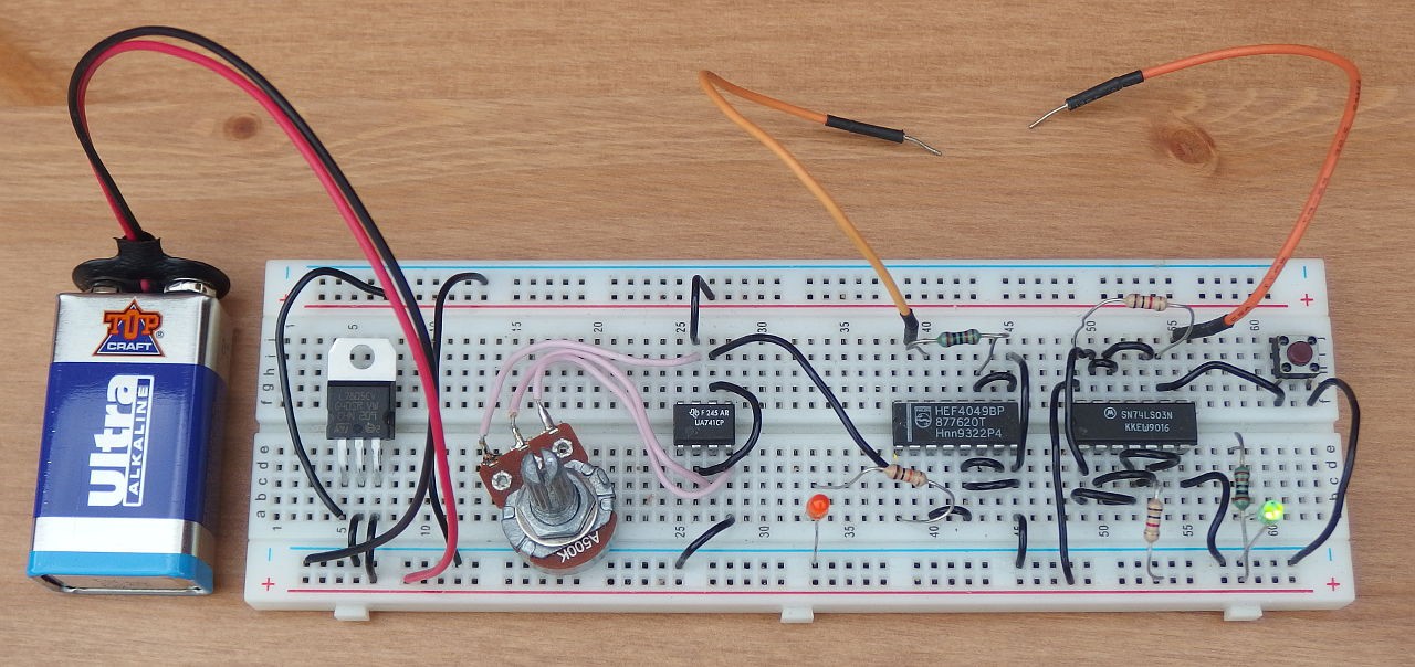
I found that this setup worked quite nicely, and by adjusting the CMOS voltage I could set the intensity of the stimulation. At 3V it wasn't noticeable, with the effect starting at about 4-5V. This will depend on the amount of moisture present. Around 6V-7V was best, with 8V being high and 9V rather too high for comfort.
So the concept of using standard logic parts to drive the rows and columns seems to work, and the use of CMOS high side and open-collector low side allows the stimulation voltage to be easily controlled. Now we need to connect these to the microcontroller.
Discussions
Become a Hackaday.io Member
Create an account to leave a comment. Already have an account? Log In.