 kodera2t
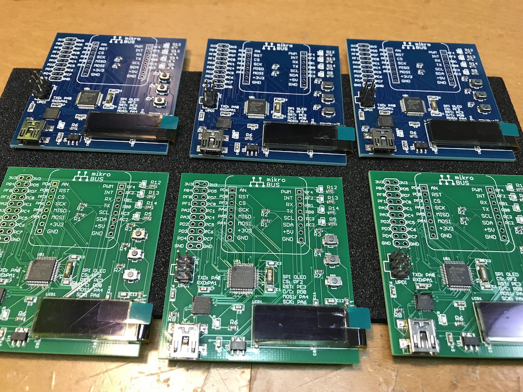
I made several experimental board (may be delivered on my tindie store) and here I would like to explain how to start project with this board on Atmel Studio with Atmel ICE.
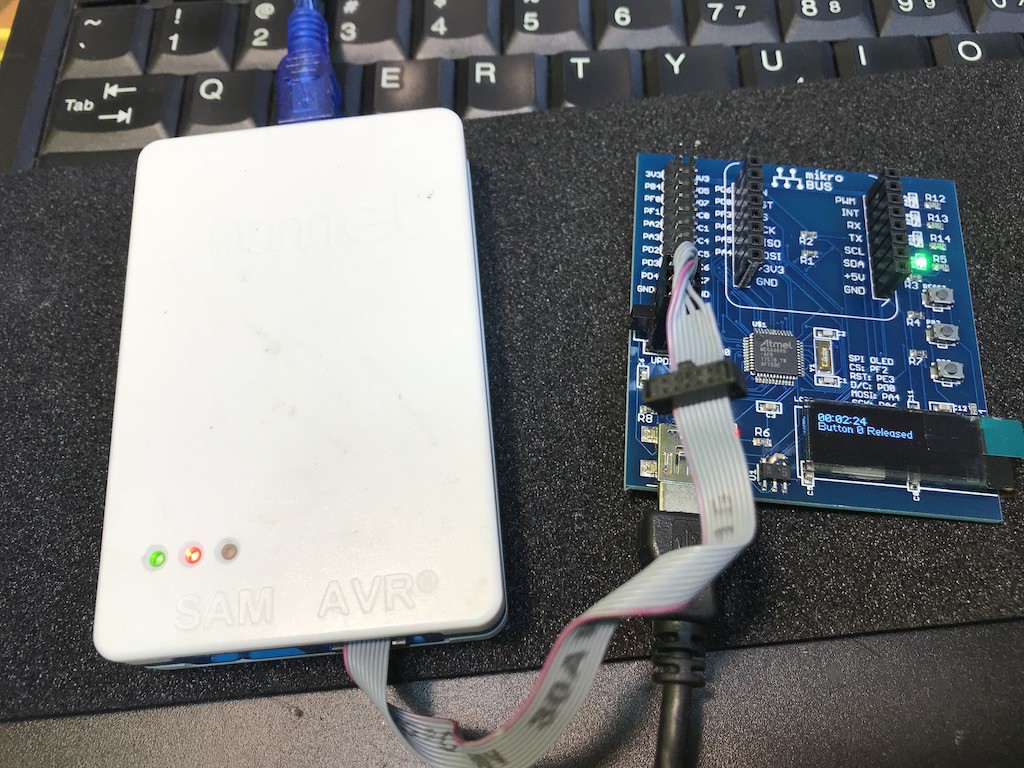
First of all, we need to install Atmel Studio (if not yet) and connect it to the onboard UPDI connector. The board is USB bus power so we need additional USB cable connection from your PC to the board.
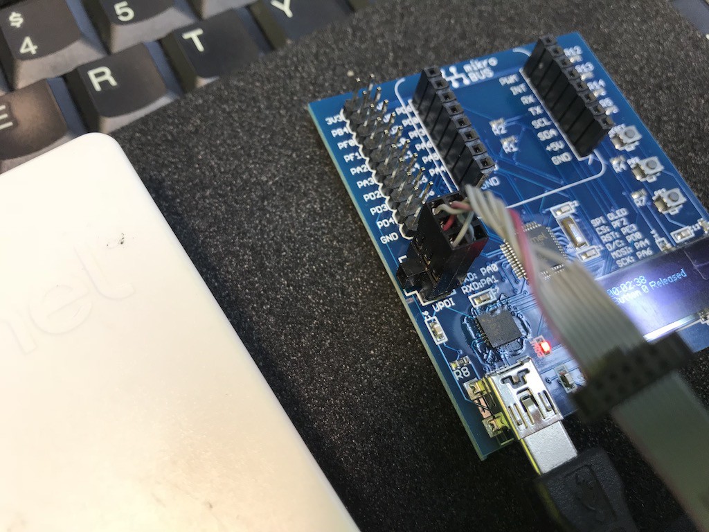
UPDI connector has a right direction so please follow the onboard guideline.
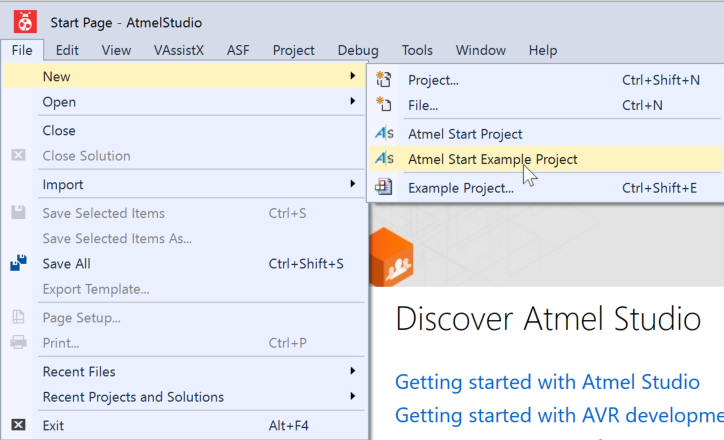
Now let's start Atmel Studio and select "Atmel Start Example Project"
and click "Browse Examples"
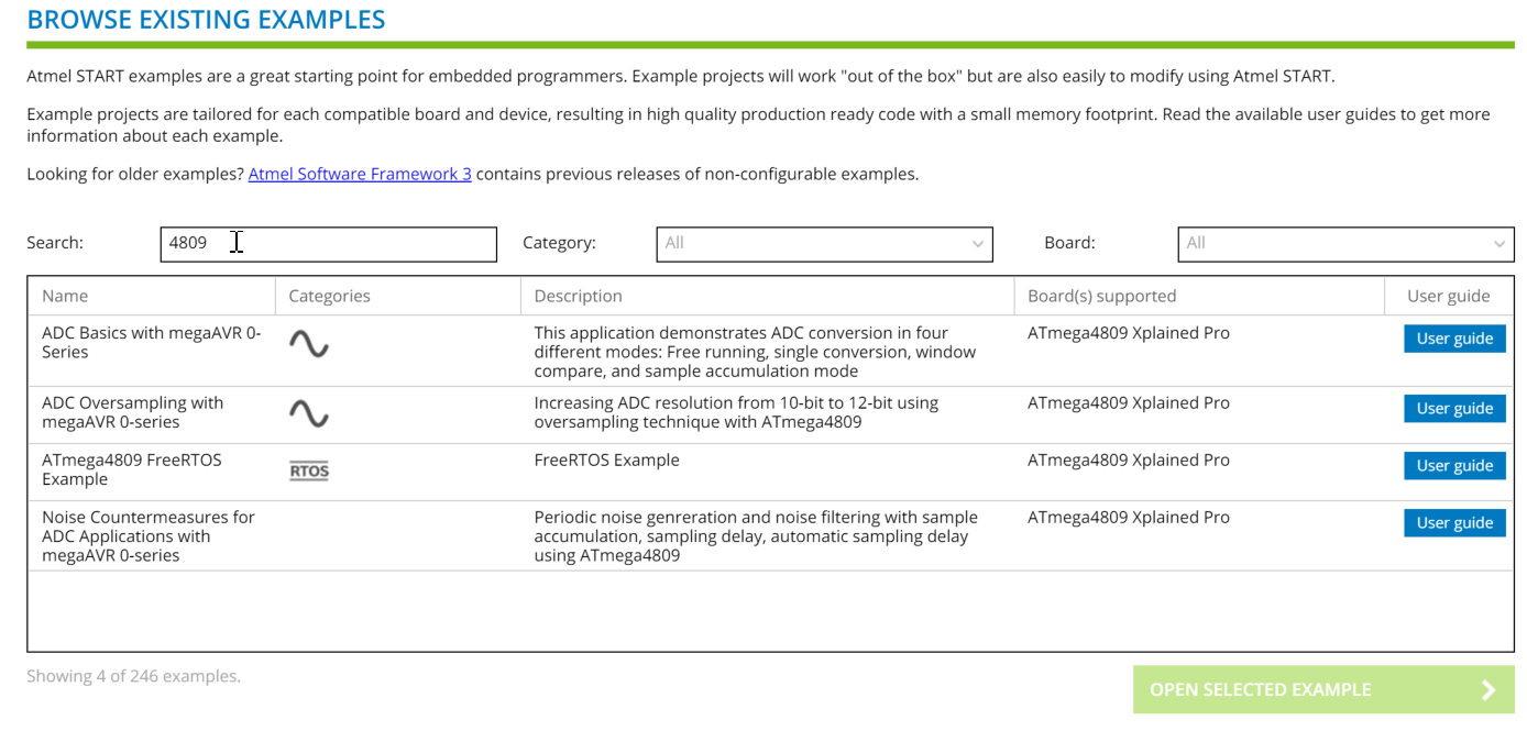
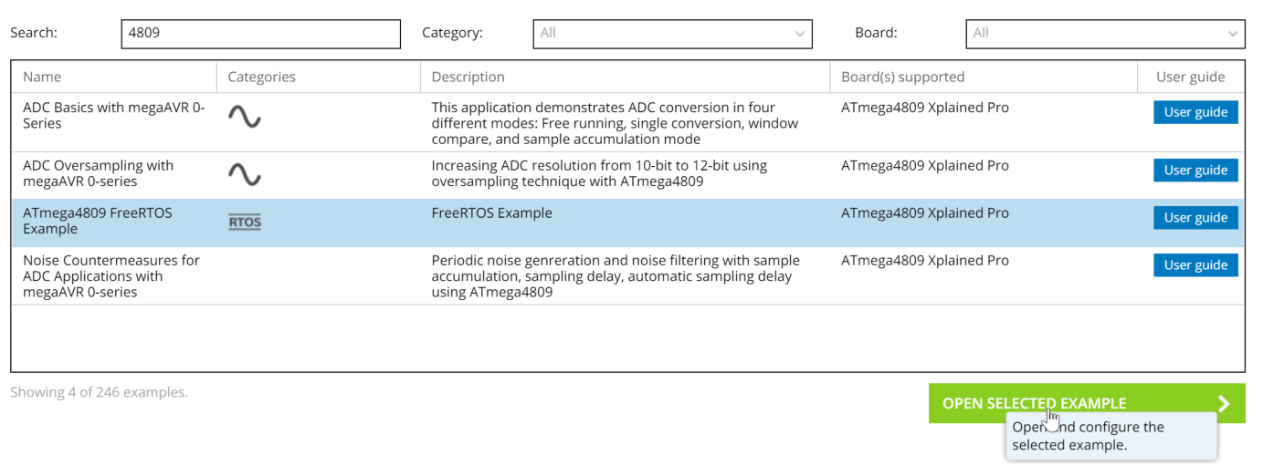
Just entering "4809" as the search word, you will find 4 examples. (still not so much, indeed.)
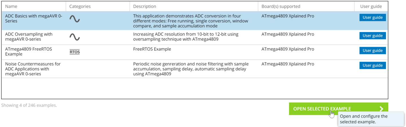
Now let's select the first "ADC Basics with megaAVR 0-Series" and click "Open Selected Example"
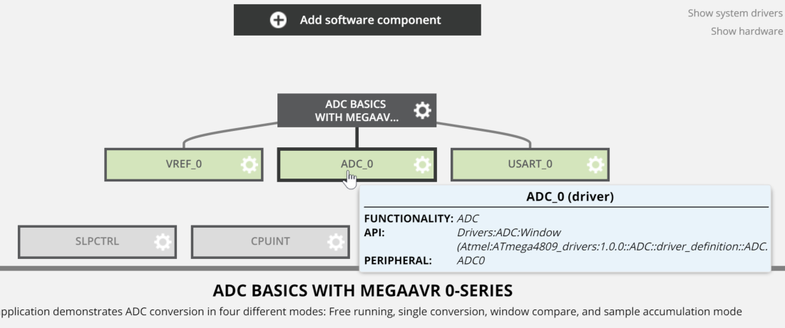
You will see this example uses three blocks, VREF_0, ADC_0, and USART_0. Now let's click "ADC_0" and see which pin is used for.
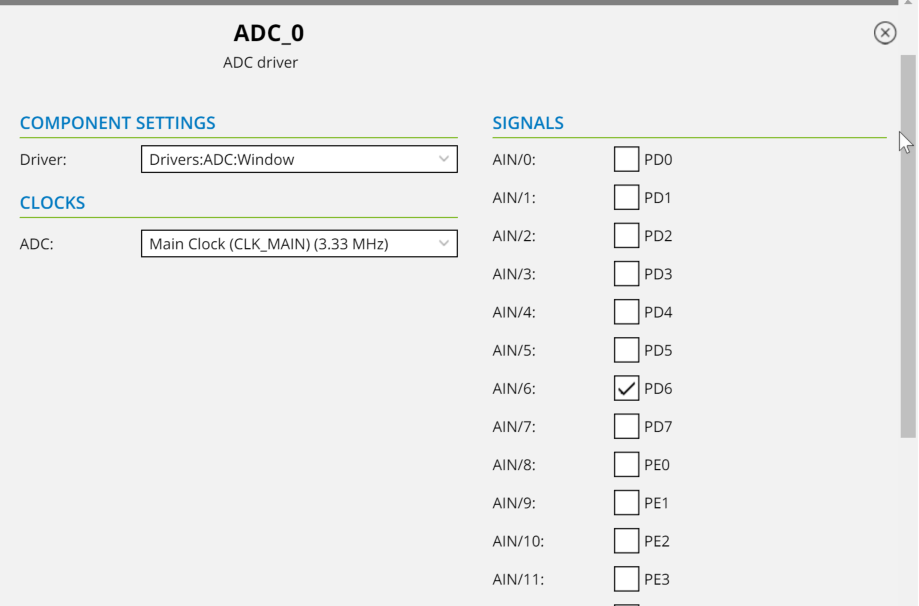
In the bottom of window, you will see the current setup for the example program. The PD6 is selected as ADC input. PD6 is "AN" of mikroBUS pinout, and it's ok for the check.
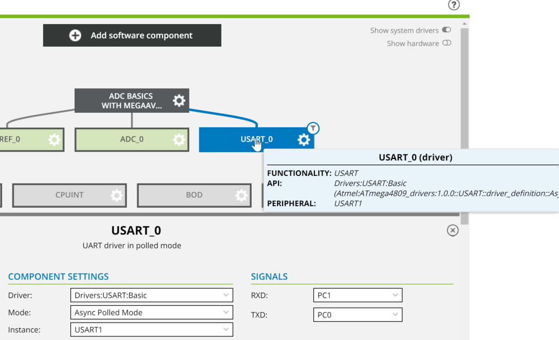
And let's switch to USART_0 setting.
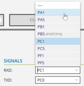
The USB-USART interface (CP2102) of "4809 Explorer board" has a connection with PA0 and PA1 so let's switch to..
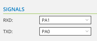
RXD to PA1 and TXD to PA0.
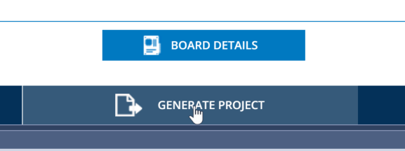
Now the online preparation is finished. Let's click "Generate Project"!!
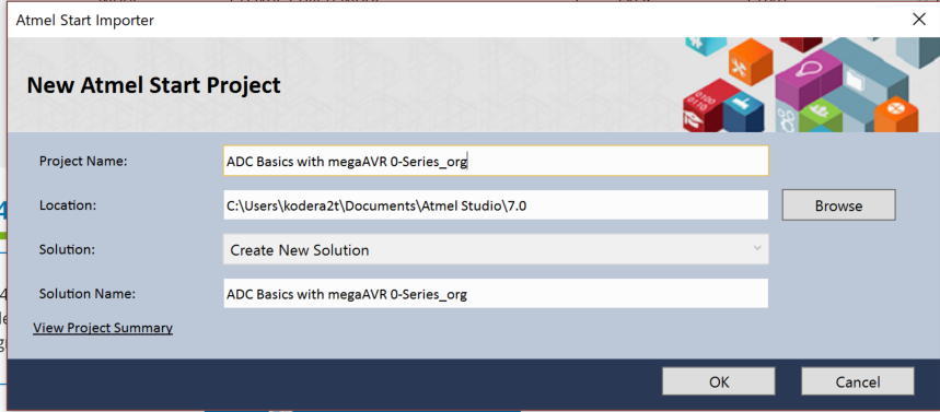
You will see the Atmel start importer windows and please name your new project name as you wish, and after clock "OK" you will see the
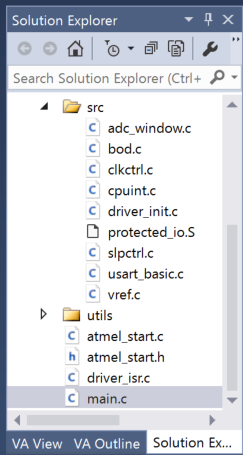
Downloaded files in the solution explorer. The files in src directory are prepared for the definition of above (like USART settings..)
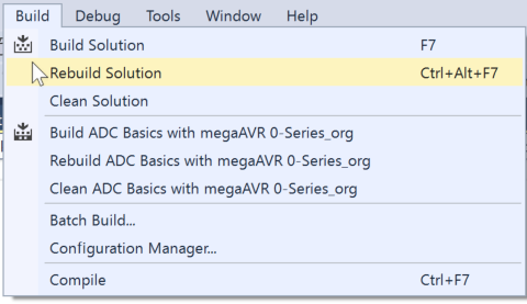
Now the source files are prepared (no need of modification) so let's select "Rebuild Solution"
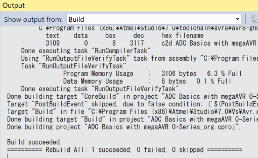
Currently the files are "as is" so it will not produce any error.
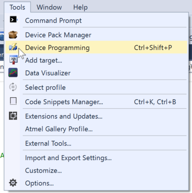
Now let's start binary uploading to the 4809 explorer...
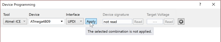
You will see the device programming window, and let's select Tool as "Atmel-ICE" and device "ATmega4809" and select UPDI as interface and click "Apply"
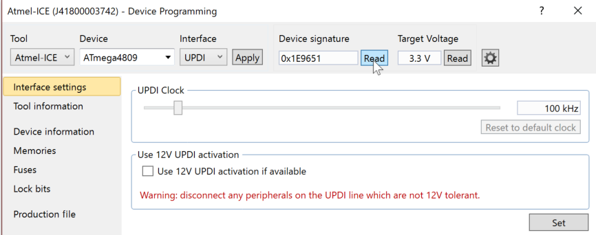
After setting UPDI clock as default 100kHz by click "Set" in the bottom-right button, let's read device signature. If it presents "0x1E9651", then the connection is succeeded.
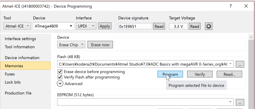
Now the time for uploading. Select "Memories" and just click "Program" will flash your board with the new binary!
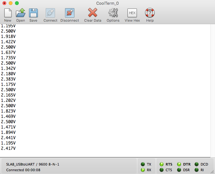
This sample program will read ADC and will output to USART, so just read USART with serial console, you will see the value of PD6(AN) pin voltage of onboard connector.
In the very the same manner, the sample with OLED display can be made by "ATmega4809 RTOS Example". Let's try!
Discussions
Become a Hackaday.io Member
Create an account to leave a comment. Already have an account? Log In.