I've decided to add networking capability to the device after much ribbing about crossing the streams.

After discussion with Doc we came to the conclusion that synchronising the streams was all we could come up with, so the networking allows the device to be social. Crossing streams with another user will result in both devices playing the Ghostbusters Theme in Midi, using the lasers to sync the timing.
The lasers themselves will affect the sensors, so I've implemented only 3 devices per network, using the 3 colours of laser I've managed to obtain. Each device has a laser and two filters, ie Red has Blue and Green filters to discriminate signals from each and block its own signals.
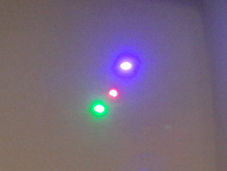
 Actually the green is by far the brightest of those, but the colours are pretty good. Slightly purple blue, but the ranges overlap nicely to give a solid white dot with all three, which hurts to look at.
Heheheh, always wanted to try that... Quick test, and then to work.
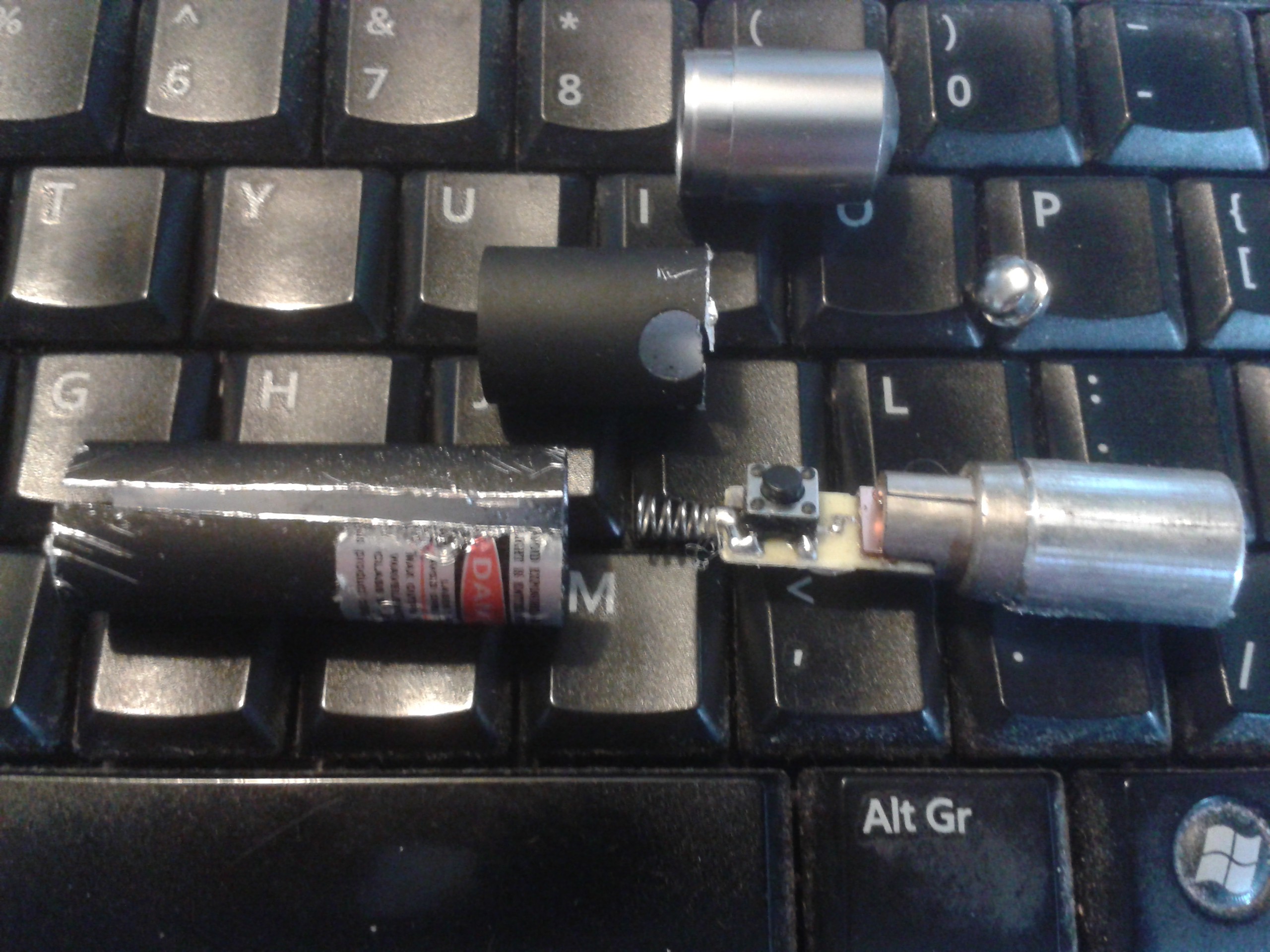
 First up, red diode. Nothing unexpected in there, these things run off a pair of AAA cells and have a small resistor to limit the current. I can just bypass the switch and pulse this one at KHz with no trouble.
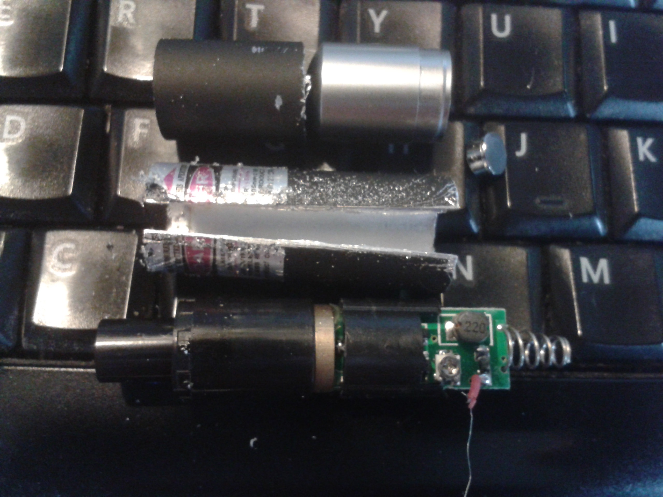
The blue one was a bit more complicated but wasnt really much trouble. The positive comes off the case and I managed to catch the lead wire contacting it with the saw. No worries, that could have been worse. All the same, it appears to have a Buck Converter to power it off the 3v supply, and cant be pulsed anywhere near as fast as the red. It shouldnt be a problem, and I can modify it to isolate just the diode to pulse it faster if it is.

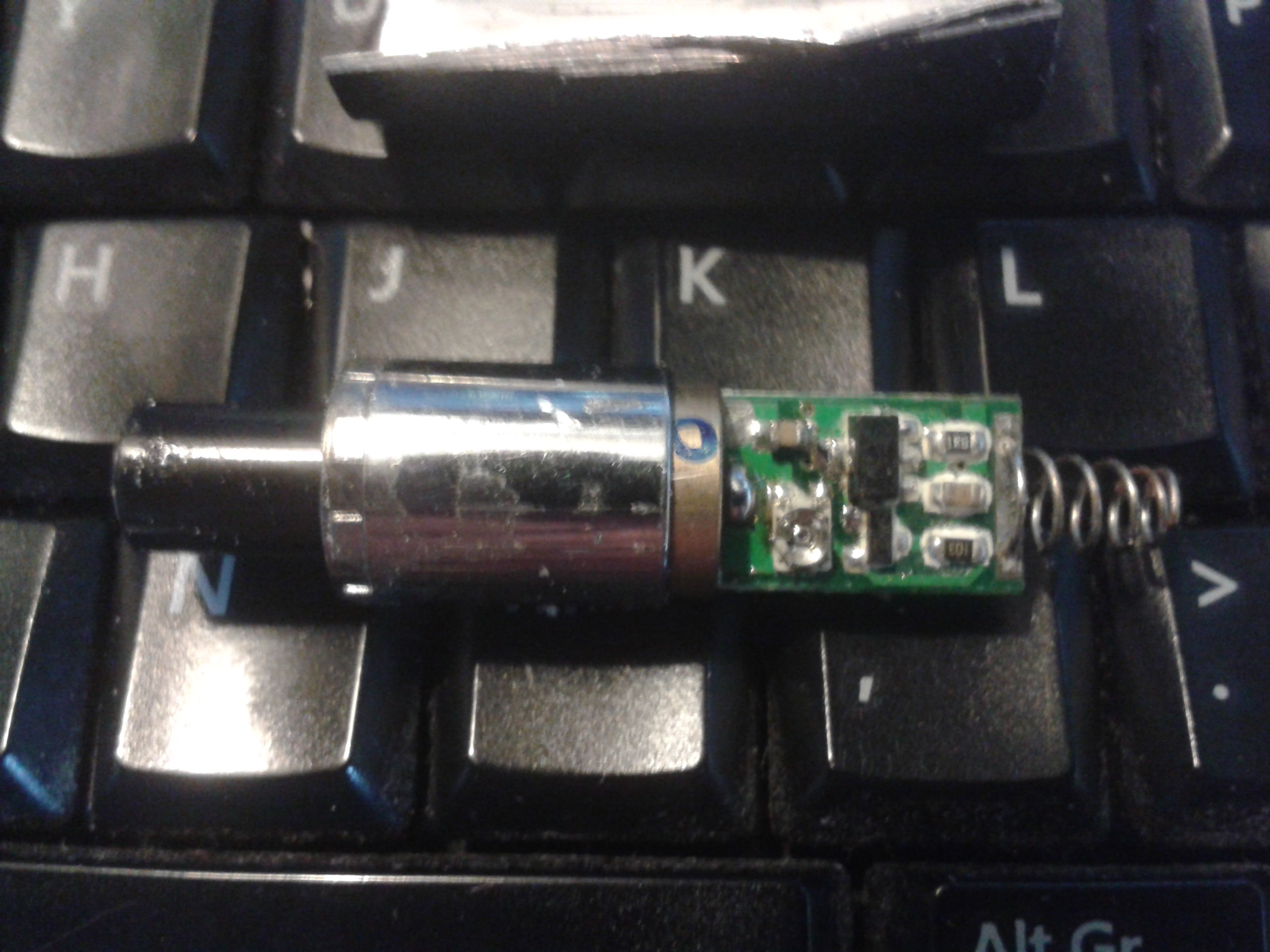
The green diode put up a bit of a fight, it was glued to the inside of the case. Again it has a power supply by the looks but I dont recognise it, not a Buck with no inductor. I can work round that the same way as the blue one if it gives me any trouble.
Midi timing signals occur at regular intervals 24 times a second using 115200BPS switching, meaning I'll need switch times way too short to use it reliably. It however occurred to me to use a microcontroller pin to power the laser, and send a lower baud rate signal. Then I can receive the two filtered signals on two more pins so it can tell them apart.
Flash rates above 50Hz are perceived as solid light by our eyes, so I can bring the baud rate right down to 25BPS if necessary, using a long duty to eliminate noise.
After much pondering on the subject, I've decided to use an Atmel 328 and run a Software Serial port alongside the hardware one.
Hardware TX will power the device's own laser, and the two colour sensors will shunt 5v to the hardware and software RX when triggered by the other lasers. This arrangement means I can send a song position byte continuously on the TX to light up the streams, and when they are crossed that song position byte is used by the other device to synchronise using device priority.
The lowest priority device becomes a slave in RGB order, so any two devices or all three will automatically play and maintain song position during any interference in the data streams.
I'm expecting a lot of splash. XD
 Morning.Star
Discussions
Become a Hackaday.io Member
Create an account to leave a comment. Already have an account? Log In.
What kind of test jig is going to be used to quality check this ;-)
Are you sure? yes | no