 hkdcsf
Objectives:
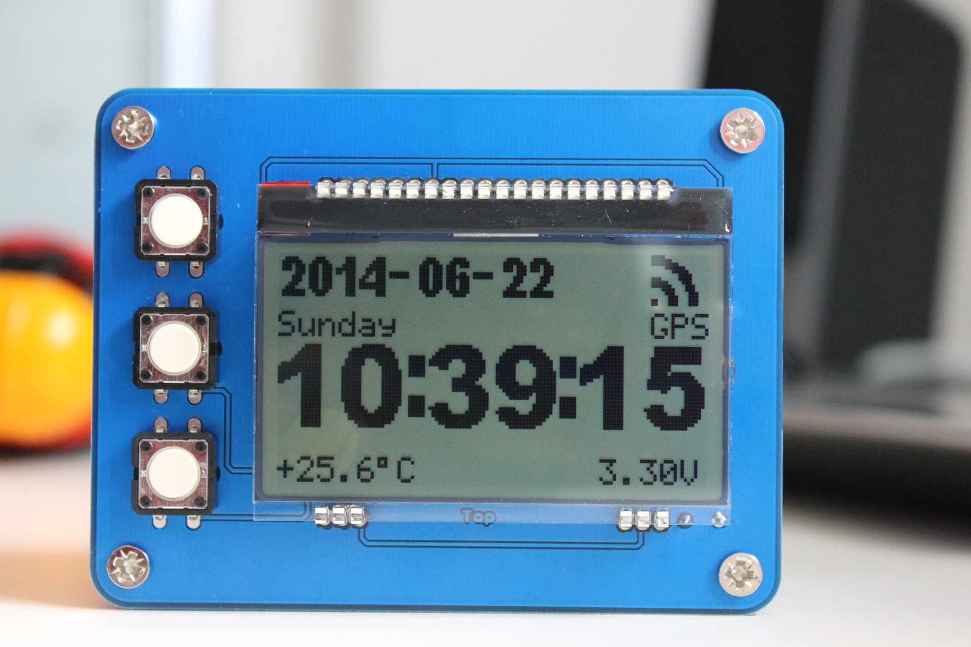
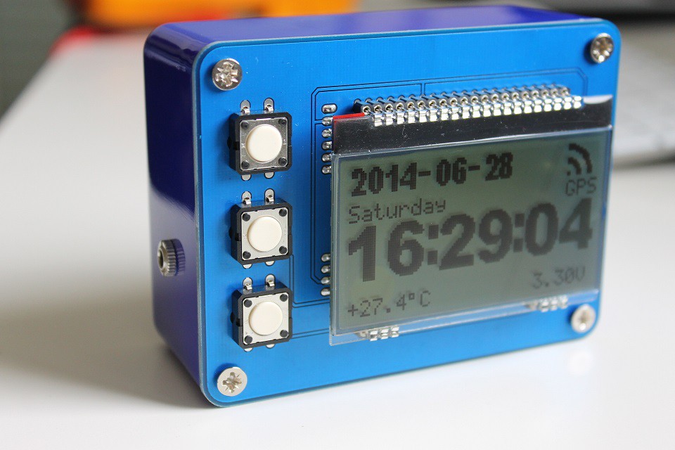
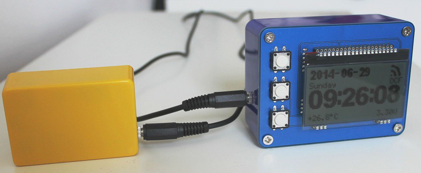
- receiving date and time from the DCF77 transmitter, decoding it, displaying it on a 128x64 pixel dotmatrix display
- receiving UTC from GPS satellites with a GPS module, displaying it on a 128x64 pixel dotmatrix display
- stand-alone date and time clock based on a real time clock (if radio signal reception is not possible)
- measuring and displaying temperature
- measuring and displaying battery voltage
- displaying SW version information
- simple menu system for configuration
- alarm function
- beep sound on button press
HW block diagram
On the picture below You can see the HW block diagram.
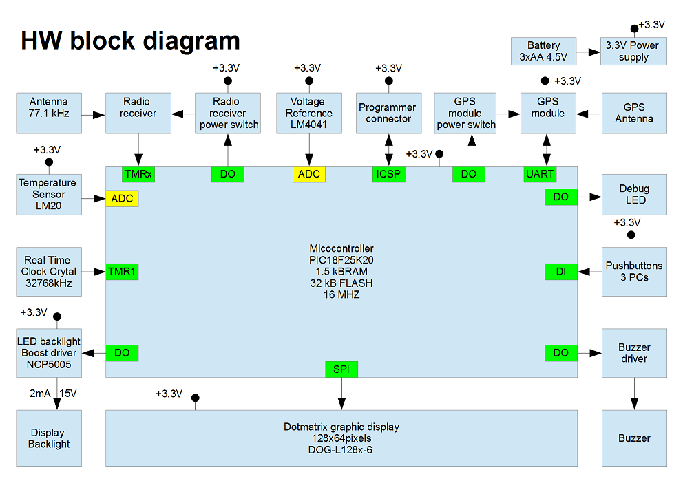
I built the project around a PIC microcontroller. The goal was during the micro selection is to have a low power consumption but yet powerful enough controller to decode the DCF77 and GPS signals and to drive the display. I also choose a type which I familiar with.
The display is a chip-on-glass type which can be powered from 3.3V. It can be controlled via a simple SPI protocol. Another advantage is that no mounting required, it can be simply soldered on the PCB, but i will use a header adapter so the display can be changed easily.
The LED backlight is powered with an NCP5005 boost driver. The clock will be running from 3 AA batteries. To decrease the power consumption the SW has to have some intelligence: dimming, or even switch off the backlight at certain time of the day.
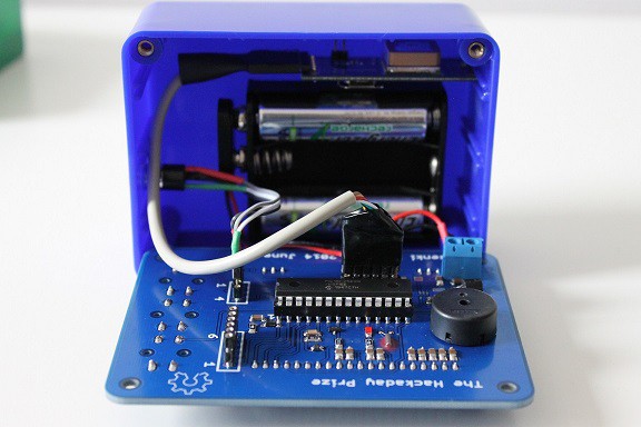
I used a small 32768 kHz real time clock crystal, so the clock can remain relatively punctual even when no DCF77 or GPS reception is possible.
For temperature measurement an analog LM20 sensor is used.
In order to measure the output of the temperature sensor and the battery voltage accurately an LM4041 voltage reference is used.
Programming and debugging is performed with a PICkit3 programmer, so a header adapter is connected to the ICSP of the micro as programmer connector.
For powering the whole circuit 3 AA battery is used and a very low drop 3.3V voltage regulator.
For easier debugging and for measurement purpose during the development a red LED is directly connected to a micro output with a series resistor.
To be able to operate the menu and set the date and time 3 taktile type push buttons is connected to 3 microcontroller inputs with pull-up resistors.
A TDK PS1720P02 piezo buzzer is used for generating a sound signal when a button is pressed and for the alarm clock functionality.
For UTC reception from a GPS satellite a PmodGPS module is used from Digilent.
For exact time and date reception a DCF 77 receiver module with digital output is used from Conrad electronics.
Schematic
On the picture below You can see the schematic of my project.

I tried to isolate the main blocks therefore I added a grey dashed line frame around them to easily identify which block is doing what.
I used Eagle 6.6.0 PCB editor for creating the schematic.
System design: GPS signal processing
What is the interface protocol of the PmodGPS module?
According to the data sheet "The PmodGPS uses sentences
based on National Marine Electronics Association (NMEA) protocols for data
output. Each NMEA message begins with a '$' dollar sign. The next five
characters are the talker ID and the arrival alarm.
The
PmodGPS talker ID is 'GP' and the arrival alarm is the specific sentence output
descriptor. Individual comma separated data fields follow these five characters.
After the data fields there is an asterisk followed by a checksum. Each sentence
should end with <CR><LF>. <CR> is the carriage return its ASCII
value is 13, <LF> is the line feed character its ASCII value is 10.
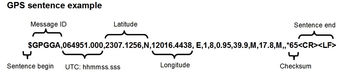
You can see an example GPS sentence on the picture
below:
 Some other examples:
$GPGGA,064951.000,2307.1256,N,12016.4438,
E,1,8,0.95,39.9,M,17.8,M,,*65<CR><LF>
$GPRMC,064951.000,A,2307.1256,N,12016.4438,E,0.03,165.48,260406,3.05,W,A*55<CR><LF>
How we receive
these GPS sentences?
Each character in the GPS
sentence corresponds to one UART (Universal Asynchronous Receiver Transmitter)
byte. The data value of this byte is equals to the corresponding...


 clewsy
 K.C. Lee
 Tobias Rathje
 Gabor
Gabor
I've tried poking with that DCF77 reciever, and it is very unstable, I had to go on my balcony to get any reception at all, indoors there is too much interference from the computer and other electronics. What is your plan to obtain a stable connection??