 leumasyerrp
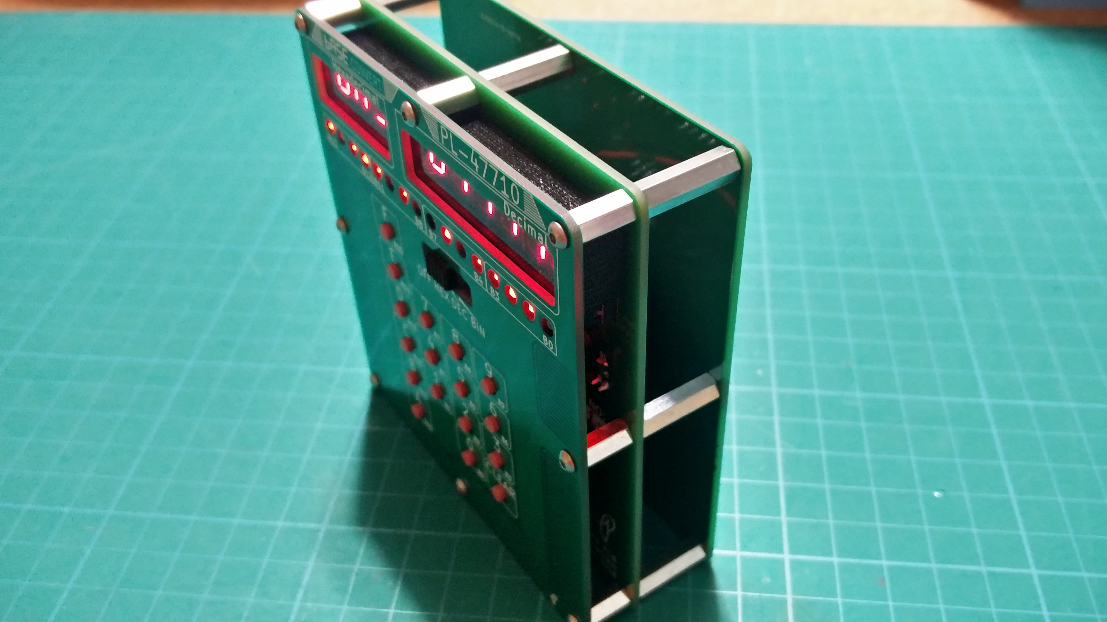
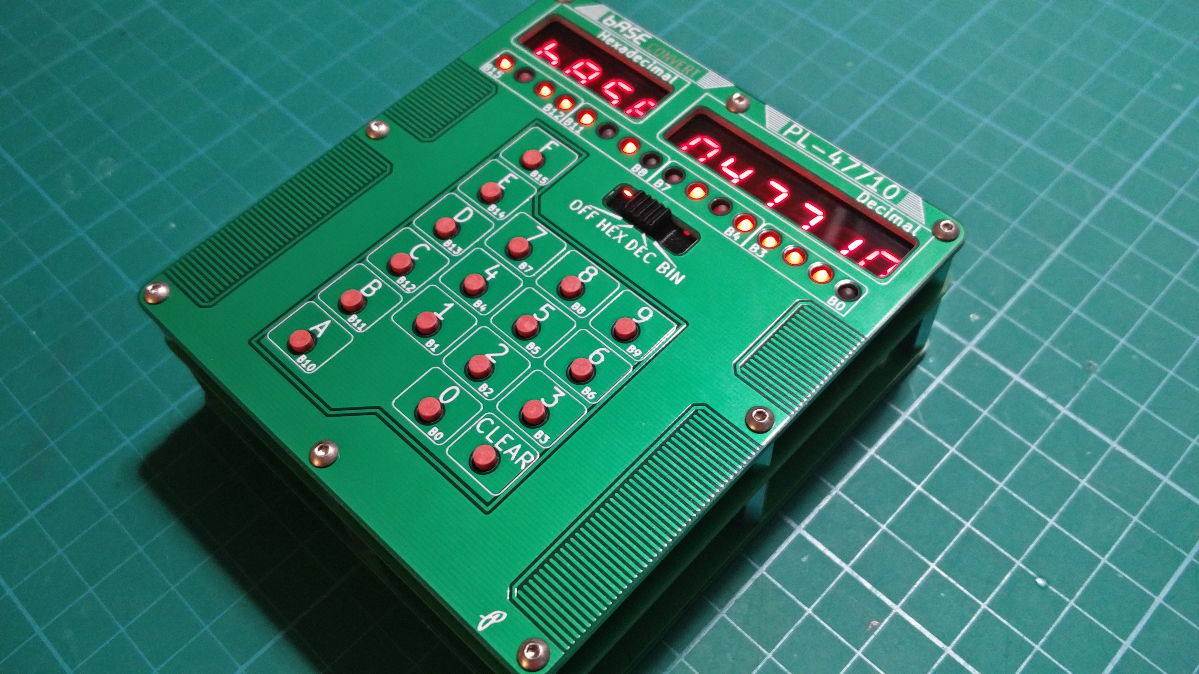
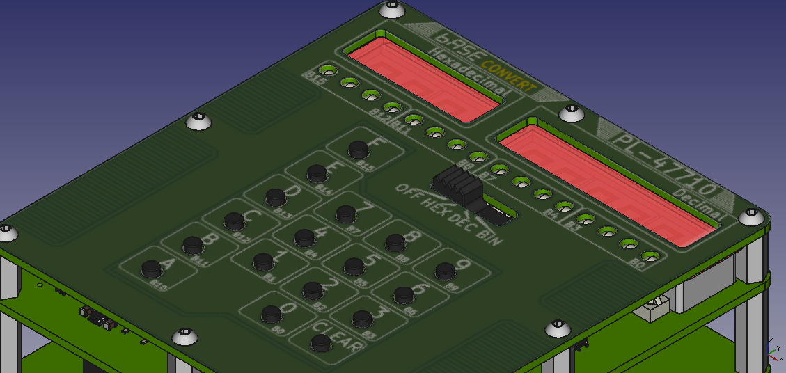
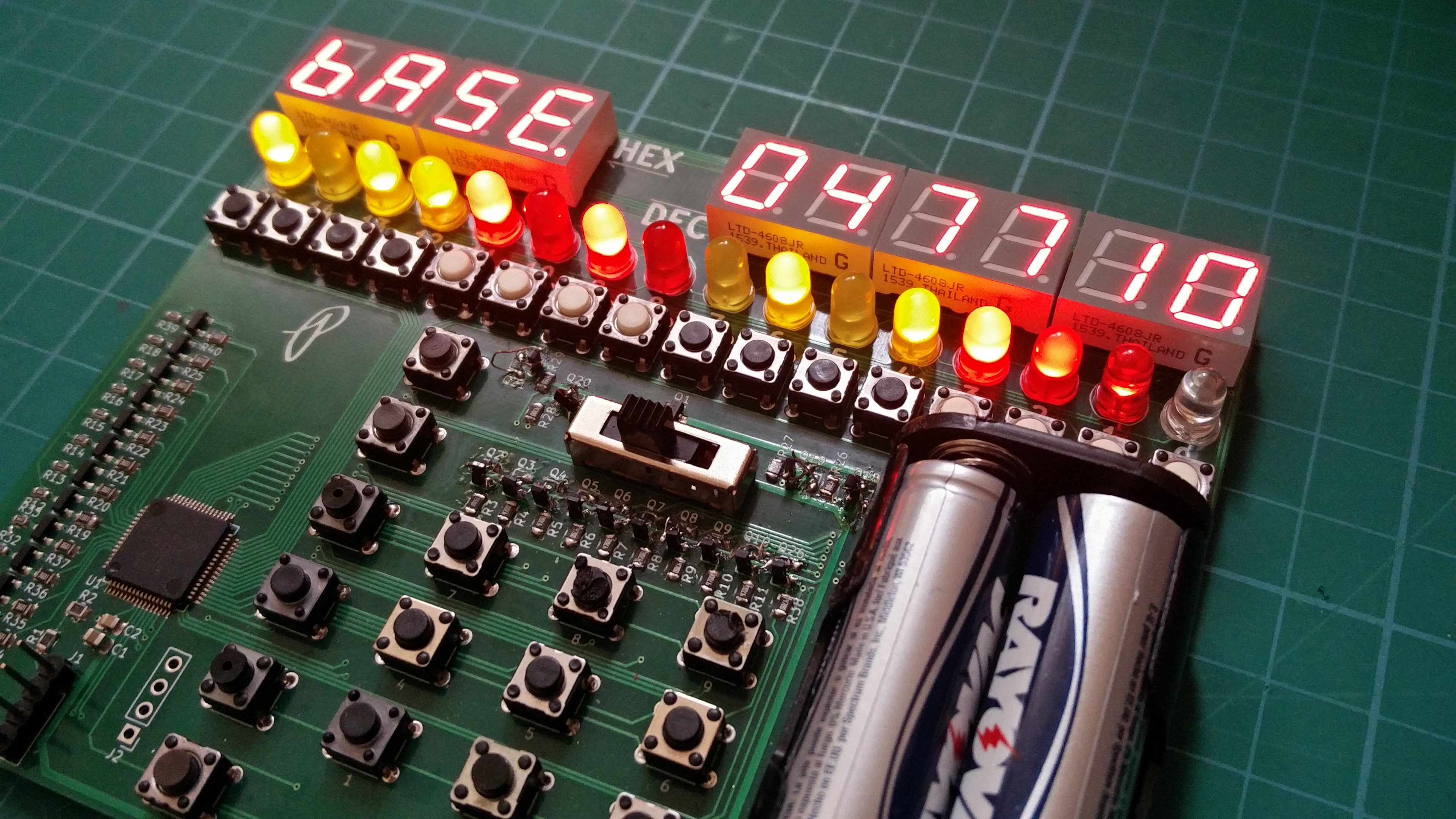
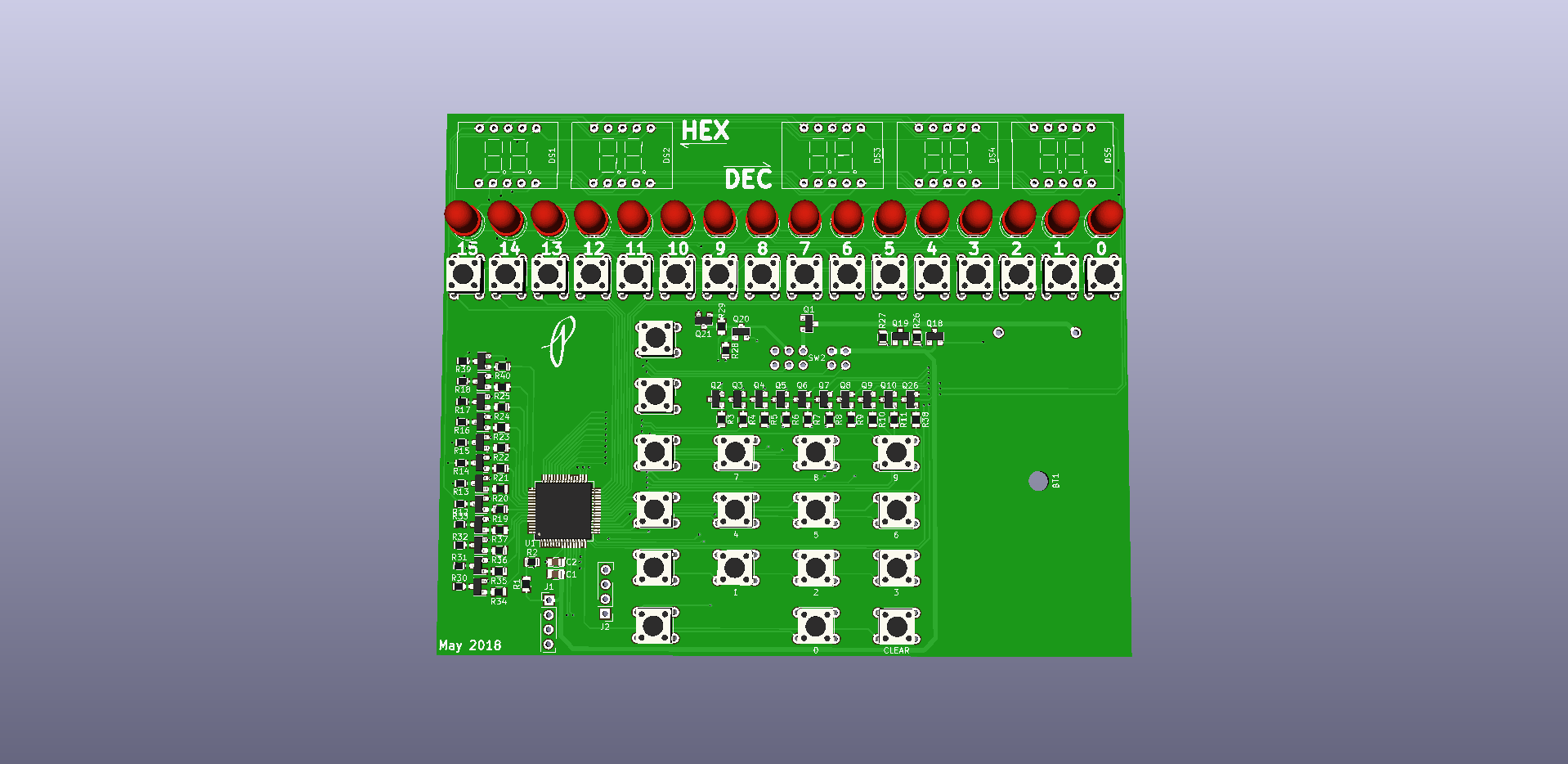
This device will convert the user input value in any of three number formats (HEX, DEC, and BIN) to the remaining number formats while displaying all formats at once. Input is accomplished by first selecting the number format using a selection switch (not pictured in preliminary render) and then using either the alphanumeric input pad or in the case of a binary number the tactile switches directly under the binary display. I want to keep this device simple with limited functionality; no games, internet connectivity, apps, ect. A stretch goal might to add some bit manipulation functions such as shifting and simple logic but that is only after the main goal is complete.
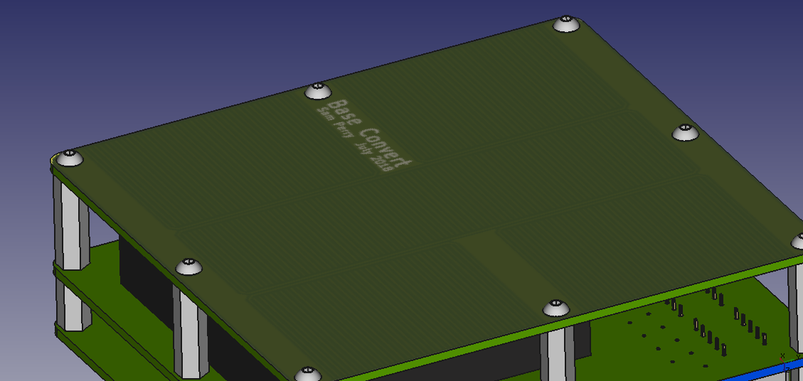
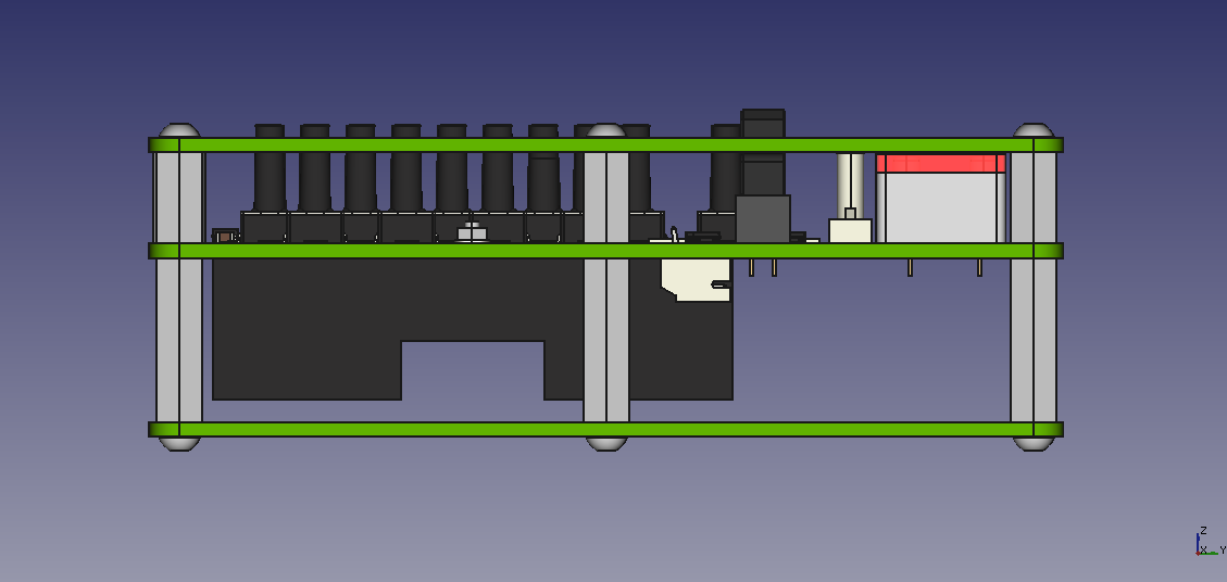
The end device will be small enough to be considered portable, the preliminary render is 106mm x 72mm but every effort will be made to make it smaller. It may end up being more of a desktop device than portable. I would prefer it to be battery powered, most likely alkaline batteries or possibly rechargeable LiPo.
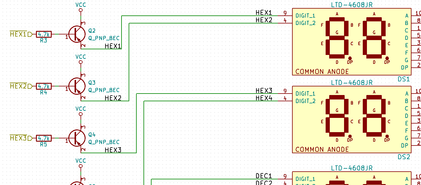
In keeping with my 2018 goal of learning programming with the MSP430 line of microcontrollers this calculator will most likely use the MSP30FR4133 microcontroller since I have a launchpad and it is a low cost high pin count microcontroller. If this uC is not suitable for this project another MSP430 will be chosen. I plan to do most of the display and input in software relying very little on supporting ICs for display driving and user input but if it makes sense to use a specialized IC I will. The MSP430FR4133 has a built in LCD driver so it maybe possible and make better sense to switch to LCD displays for HEX and DEC output but I prefer 7-segment LED displays, they just look cool.


 Michael Wessel
 Enrico Gueli
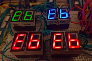
 John Lonergan
 Mastro Gippo
This is beautiful. I'm going to start saving up now to purchase one.