 leumasyerrp
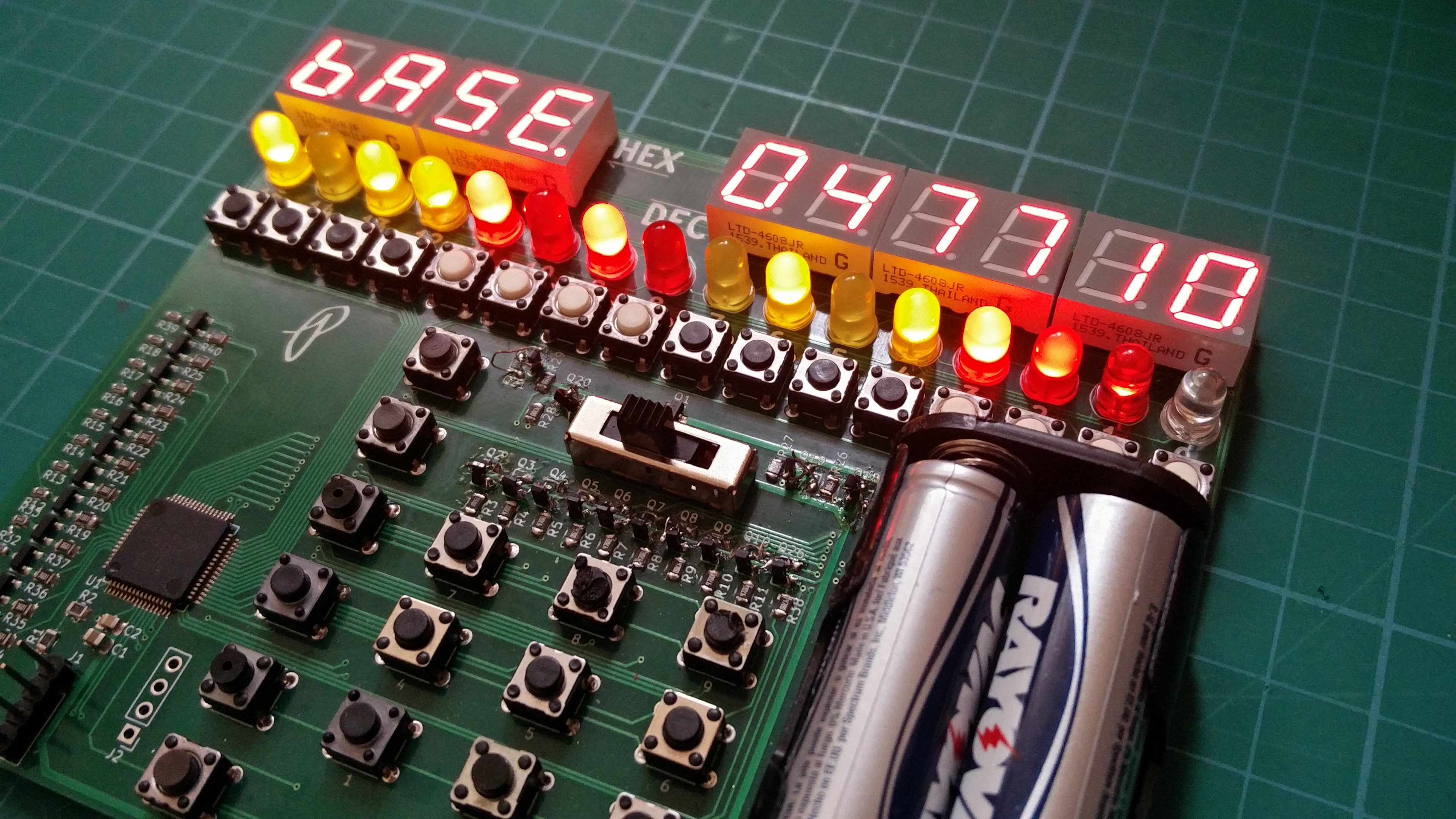
I finally got the boards assembled and have completed usable firmware that does more than just test out the display. I may be biased but I am liking what I created. The current firmware (available on GitHub if you want to see my inefficient coding skills) allows input of hexadecimal, decimal, and binary numbers using the keypad for the HEX/DEC and the buttons under the binary display for binary input. After finding some faulty tactile switches the inputs work very well considering the mess of code polling them. There is also a clear button along with an input mode selection switch that also acts as the power switch.
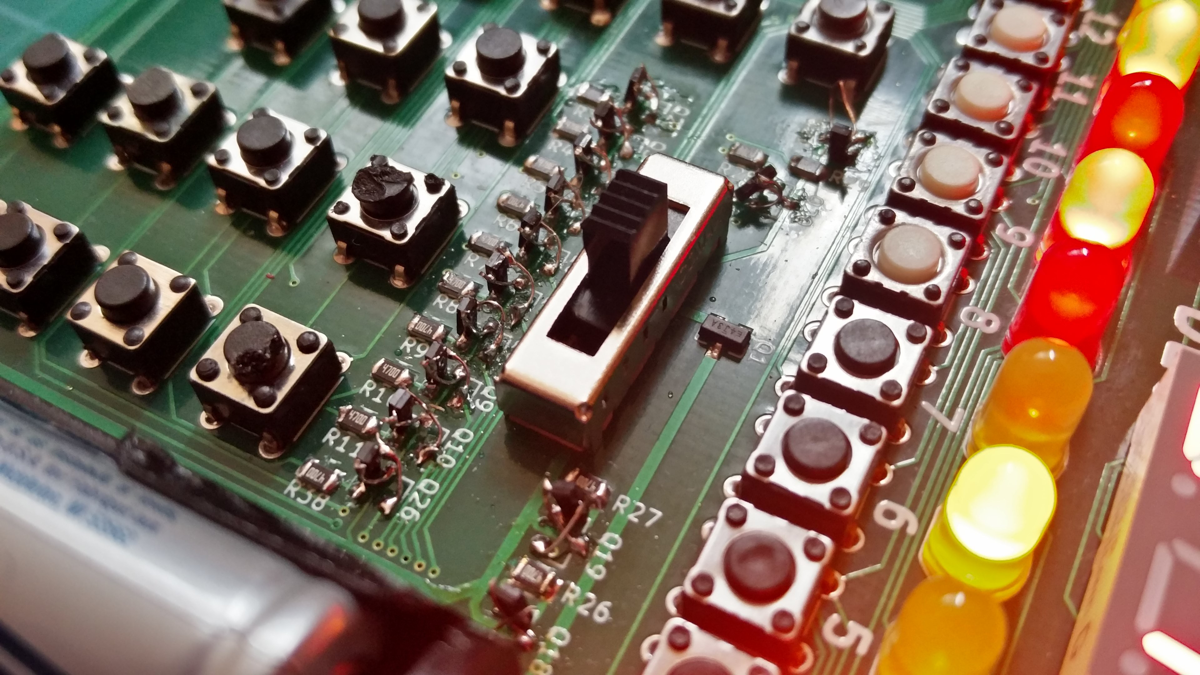
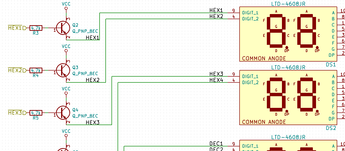
I ran into a few issues with the hardware and firmware that will have to be updated in the next PCB. For starters I must have completely forgot how to wire up a PNP transistor when capturing the schematic since I connected the collector to Vcc and not the emitter. This was the cause of a dim display that had me stumped for a few hours. I even dragged out my copies of The Art of Electronics 2nd and 3rd edition to read through the first few sections of the chapter about bipolar transistors and it was only after I sat down with pen and paper to see if I had chosen incorrect resistor values that I glanced at the PNP transistor hookup reminder on my trusty Adafruit PCB ruler that I noticed that I had wired them up wrong in the schematic. I searched on Digi-Key hoping to find SOT23 PNP transistors with BCE pinout with no luck. I ended up flipping the transistors on there ends and soldering thin magnet wire connections.
This will be fixed immediately and hopefully will be something I don't forget to check not just for this project but for future ones.
Another major issue, but this one is not circuit breaking, is that I should have wired up the keypad to ports 1 and 2 only since they are the only ports on the MSP430FR4133 with interrupt capabilities. I wrongly assumed all pins could generate an interrupt but was soon proved wrong when Code Composer Studio when WTFLOL at my attempts to enable interrupts on ports 8 and 5.

Speaking of buttons I think the next revision will have the binary and keypad share the same pins. Maybe I can get fancy and disable the keypad not being used for the current input mode using external circuitry but I would not count on it. It may not be and issue if the bit0 button also inputs a 3 during hex/dec mode.
I also have some layout to fix so that it is easier to press the buttons. Why did I place the battery holder on the top where it can block access to buttons? I may also rethink the BIN display along with the input for the BIN display. Thouse 16 buttons take up a lot of space and make the board size unnecessarily wide. I was toying with using the keypad as input, ie key 9 would toggle bit9. I don't know though, I like toggling the bits with the key right under them.
If anyone reading this knows of any PNP bipolar transistors in a SOT23 package where pins 1-3 are base, collector, and emitter respectively let me know. It would be nice to not have to throw away the 4 remaining prototype PCBs.
Discussions
Become a Hackaday.io Member
Create an account to leave a comment. Already have an account? Log In.