 zakqwy
[update 1/15/2016]
Periodically, I notice in my email that someone has "liked" or "skulled" this project. Awesome, but... sadly, as mentioned in the last log update (more than half a year old, as of this intro), I pretty thoroughly killed this power supply through my own stupidity and haven't actually pulled the thing off the shelf since. I eBay'd a nifty old HP bench supply, and most of my stuff is USB powered, and... well, I just haven't needed it since. Either way, if I were to do it all over again, I'd probably start from scratch instead of doing a conversion.
In any case--if you're looking for a DIY power supply project, I suggest checking out @Stefan Lochbrunner's excellent list: https://hackaday.io/project/4335-bench-power-supply-musings
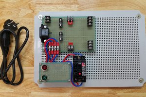
I'm pulling together pictures I took of the build process; the circuitry is super duper simple, so most of the tips I can offer are centered around hardware concerns (it's a bit of a tight fit). Hopefully you can learn from my careless mistakes and build an even better cheap power supply.
I'll probably mention this a few times, but safety is a concern with this project; switchmode power supplies operate directly on 120vac mains, and it's not always cut-and-dry where the circuit board is potentially dangerous. Worse, as compared to standard transformer-type supplies that operate on 60Hz AC, these units tend to have large capacitors on the high voltage side that can be lethal for days or weeks after the power supply is unplugged. My supply has an insulating sheet under the board that I didn't remove; in fact, I never took the main board out at all, as all of the modifications were to the metal chassis or the low voltage wiring side. My supply had also been unpowered for over a year, so there likely wasn't much left in the caps. Even so, I treated the board as if it were a live high-voltage circuit.
In other words: don't mess around with this stuff unless you know what you're doing.


 Victor Joo
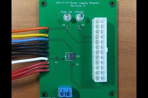
 Dave's Dev Lab
 jag
jag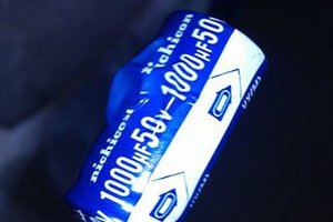
 Jakob Wulfkind
Thanks for the shoutout! I'm glad you approve :)