 Michael
THIS IS NOT USED IN THE FINAL PROJECT. IT IS PROVIDED ONLY FOR REFERENCE. THIS WAS THE ORIGINAL PLAN BUT WE HAVE HAD TO CHANGE OUR IDEAS TO MAKE IT BETTER. For information on the new charging circuit see the project log labelled "Testing, Testing 123"
Now we had the schematic of the control board sorted, it was time to make it MUCH smaller. Using the schematic we had worked out using a multimeter, we placed the main IC onto the board and, using only a Stanley knife and a fine pair of tweezers, we remade the board. The board measures 16mm x 8mm and is shown next to a 5 pence piece for reference. The wire will probably be replaced at some point but it’s the only stuff we had lying around.
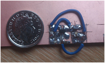
While extremely tricky to solder, this was completed in about 1 hour with the two of us and does work. Again, the only tools used were a Stanley knife to cut the board into islands to solder the components between and a fine pair of tweezers to hold them.
This was managed with only 1 injury, a minor burn on Mike’s finger but otherwise it went about as well as we could have hoped (especially as this was Mike’s first time within 100ft of a soldering iron!). This shows that even with tiny surface mount components (see the tiny black blob at the end of the arrow, that’s one of the resistors!) it is still possible to be used without a circuit board.
Good news, the wireless display components have arrived today and Mike’s been writing more code so we hope to have some more updates for you over the weekend. Unfortunately, the parts for the optics have taken longer than promised to arrive so we will aim to post a video showing how those work about the middle of next week.
Discussions
Become a Hackaday.io Member
Create an account to leave a comment. Already have an account? Log In.