Close
0%
0%

Lead Acid Ah Capacity Tester/Logger

A genuine, automatic load tester that requires no heat sinks and can be built in 2 hours with all through hole parts. Based on a PIC 16F uC.

Similar projects worth following
Based on a pulse width modulation approach, this DIY Amp Hour capacity tester logger can handle up to 10A or 120Watt loads with NO LOAD heat sinking or forced cooling. It uses dichroic lamps as modular, swappable maximum loads. The 2 button control permits calibration and 8 steps of load settings. Good to a maximum 127Ah of data logging in this version. Minimum suggested battery size is around 4Ah. This covers most UPS, security backup, motorbike,auto and a lot of marine batteries. Digital display and LED indicators. Commonly available parts! Available as a complete kit from ClubJameco as well.

The two digit displays a few things.
1) Alternate battery voltage Integer & decimal for precise voltage calibration to compensate for cabling & connection losses . eg 12.74
2) Single integer & decimal for current load setting up to 9.9A.
3) Cumulative Ah while running.
4) Undervolt 'Lo', to avoid testing an undercharged battery.
5) Hi Ah >99 - 'Hi'
6) 'UP' when ready to uplink the discharge log to PC

The Design files link contains build instructions, How it works, , BOM, HEX code and parts sourcing from Jameco.

  • 1 × See the EXCEL file in the archive for a BOM

  • Cabling AWG & length

    mosaicmerc04/20/2015 at 19:23 0 comments

    Please note that for higher currents >8A you must use SHORT cables , perhaps 1' each and #14AWG or larger. Otherwise voltage bounce can destroy the FET driver in a minute!

  • Version 1.1

    mosaicmerc03/04/2015 at 01:09 0 comments

    A user (Dennis Rieger) discovered that when running high loads around 8.5A over a number of hours, radiant heat from the nearby lamp and current sense resistor can cause the MOSFET driver to overheat, output poor gate drive and then that can take out the MOSFET.

    While that hasn't happened to me, the lamps I use may have better silvering on them which sidesteps the problem.

    I did a board redesign and accommodated space for a small heatsink on the IRF3205 NFET (improved from the Z44) and made room for aluminum (soda can) material or brass (craft) sheet to be used as radiant heat deflectors.

View all 2 project logs

  • 1
    Step 1

    See the design files link under the images sidebar for complete files and instructions!

View all instructions

Enjoy this project?

Share

Discussions

mosaicmerc wrote 02/21/2015 at 00:13 point

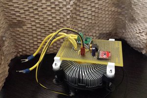
A board redesign is underway as some lamp loads get quite hot and  cause the FET driver to fail due to its' proximity to the lamps and load resistors. The updated layout will bump the FET to a heavier duty unit  and provide space for a small heat sink and a radiant heat shield  for the FET and the FET driver.

  Are you sure? yes | no

mosaicmerc wrote 03/13/2015 at 16:09 point

The design files are updated to permit 'heavier' loading for larger batteries.

I'll look at new firmware to permit up to 225Ah (currently 125Ah) battery testing as well.

For some reason Jameco has not reactivated the sale of this kit....down since January. So, DIY is the only way for now.

  Are you sure? yes | no

mosaicmerc wrote 03/31/2015 at 00:36 point

Update is complete and Jameco kit updated.

  Are you sure? yes | no

mosaicmerc wrote 04/10/2015 at 20:39 point

The updated logger is now available as a kit: Jameco.com p/n : 

2209668

  Are you sure? yes | no

Similar Projects

Does this project spark your interest?

Become a member to follow this project and never miss any updates