 jaromir.sukuba
Intro
There are various systems of fiber optic sensors (sensing mostly non-electric parameters, like temperature, mechanical strain or pressure), many of them using fiber only as data medium, while the active part is electronic or mechanical based.
The most most proggresive ones use modified fiber itself as sensor. Having fiber-only (intrisic) sensors - with no electronics involved in sensing area - brings many advantages. One of them is unability to affect measured object, having advantage in biological experiments (no electrical fields) or even in combustive environment (no risk of electric spark). Another advantage is immunity to electrical or magnetic field, so those sensors could be used - for example - to measure strin on high-voltage electric lines or thermal gradients in power transformers. What more, optical snesors allow to separate measured area and data measurement system with huge distance, with distances as long as few kilometers or more. Such as advantages are hard to workaround with electric-only systems, that's why those sensors are used for marine, aerospace and military eqipment, as well as for structural health monitoring of big buildings or bridges.
Having optical-only sensor brings also some challenges in datalogger (term interrogation system or interrogator is also used) design, as it deals with both electric and optic components. Those tend to be quite expensive (tens of thousands of USD), sensors itself are not very cheap as well (tens to thousands of USD) and price of equipment to manufacture the fiber itself has usually more than six digits.
Goal of the project
Aim of this project is to prepare completely open and cheap solution to manufacture sensitive fiber for sensor as well as optical interrogator to complete optical-only measurement system to measure temperature or mechanical strain, with price under 123USD (no special value, I just like the number and it is around 100-150USD price tag).
Some more details
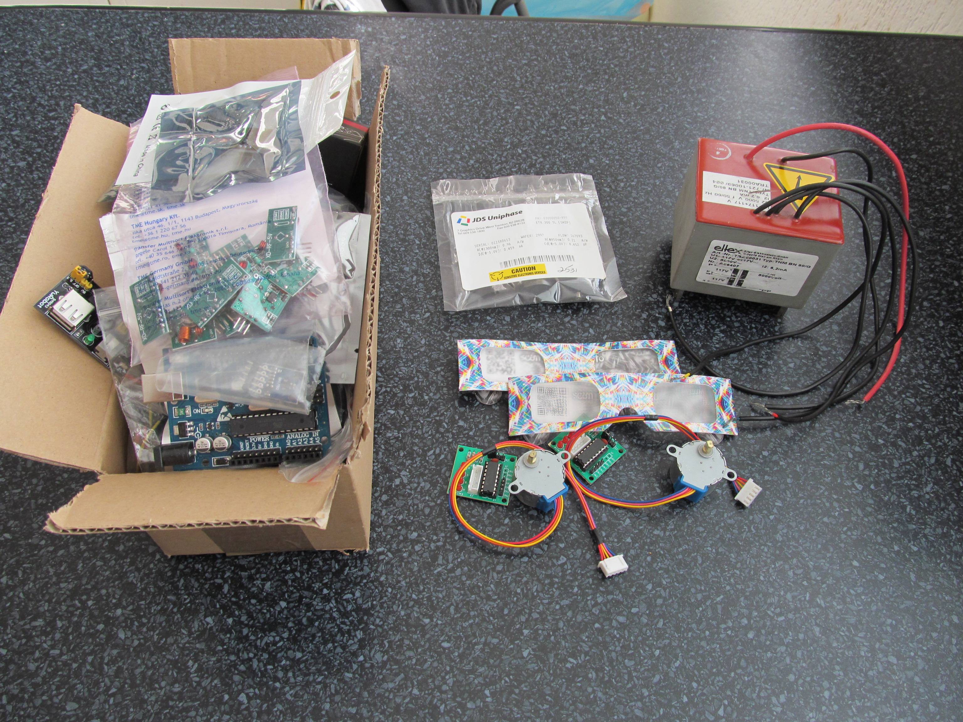
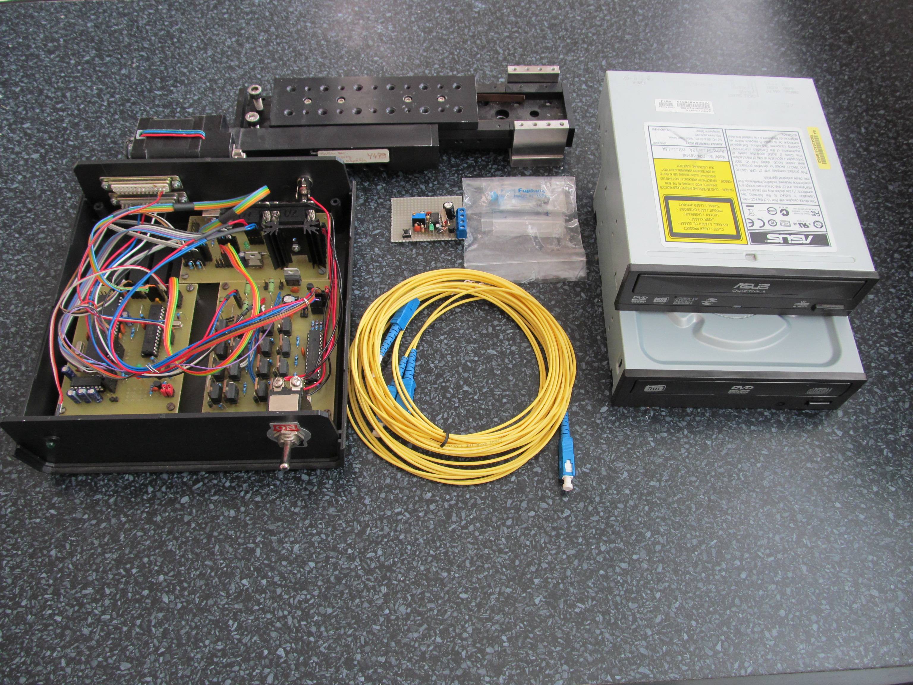
I'm going to use as much of open-sourced technology as possible, make the parts 3D printable, use multiplatform firmware (to allow running on ARM/PIC/Arduino/whatever with minor modifications) and buy available and easy to obtain parts.
Before looking at the project details, it is worthy to look at the theory behind the sensors, it will not hurt. The project is divident into two tasks:
1, The fiber optic sensor manufacturing, with help of dedicated rig
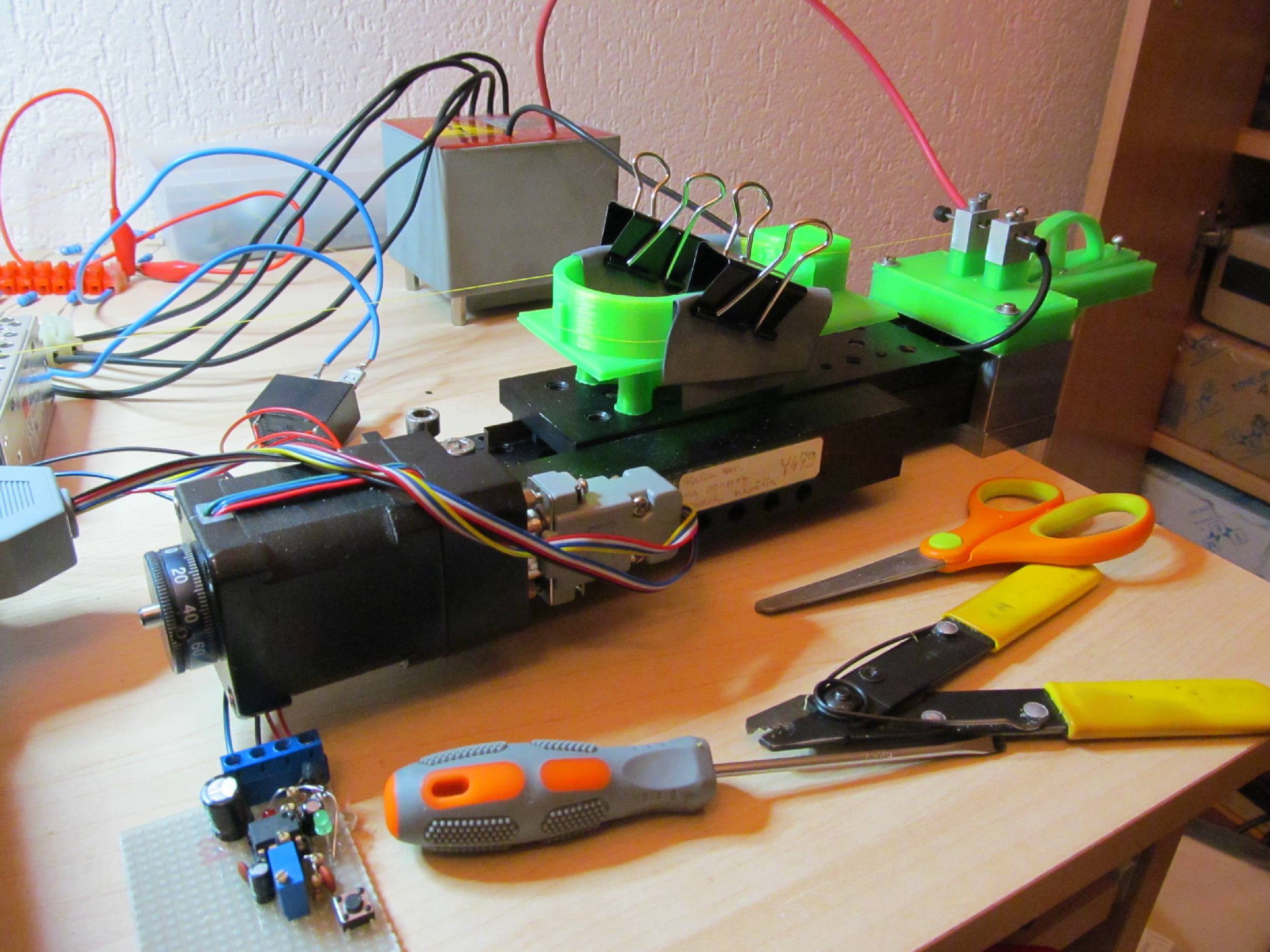
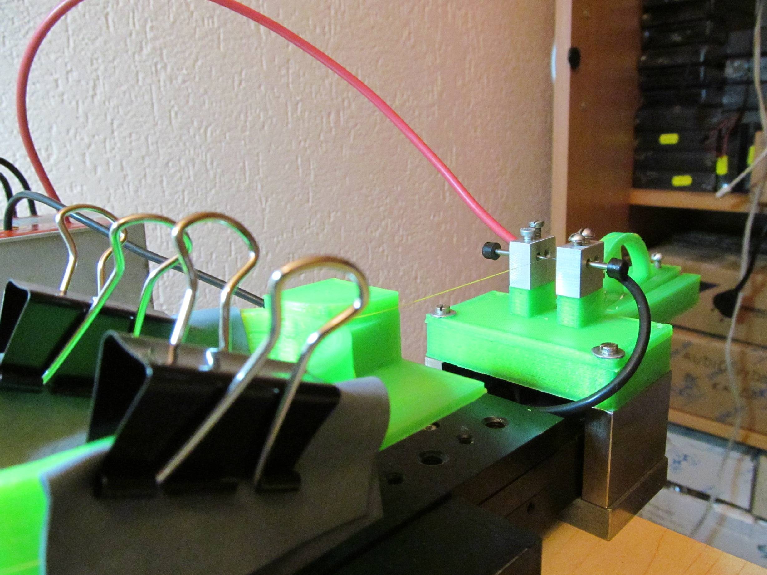
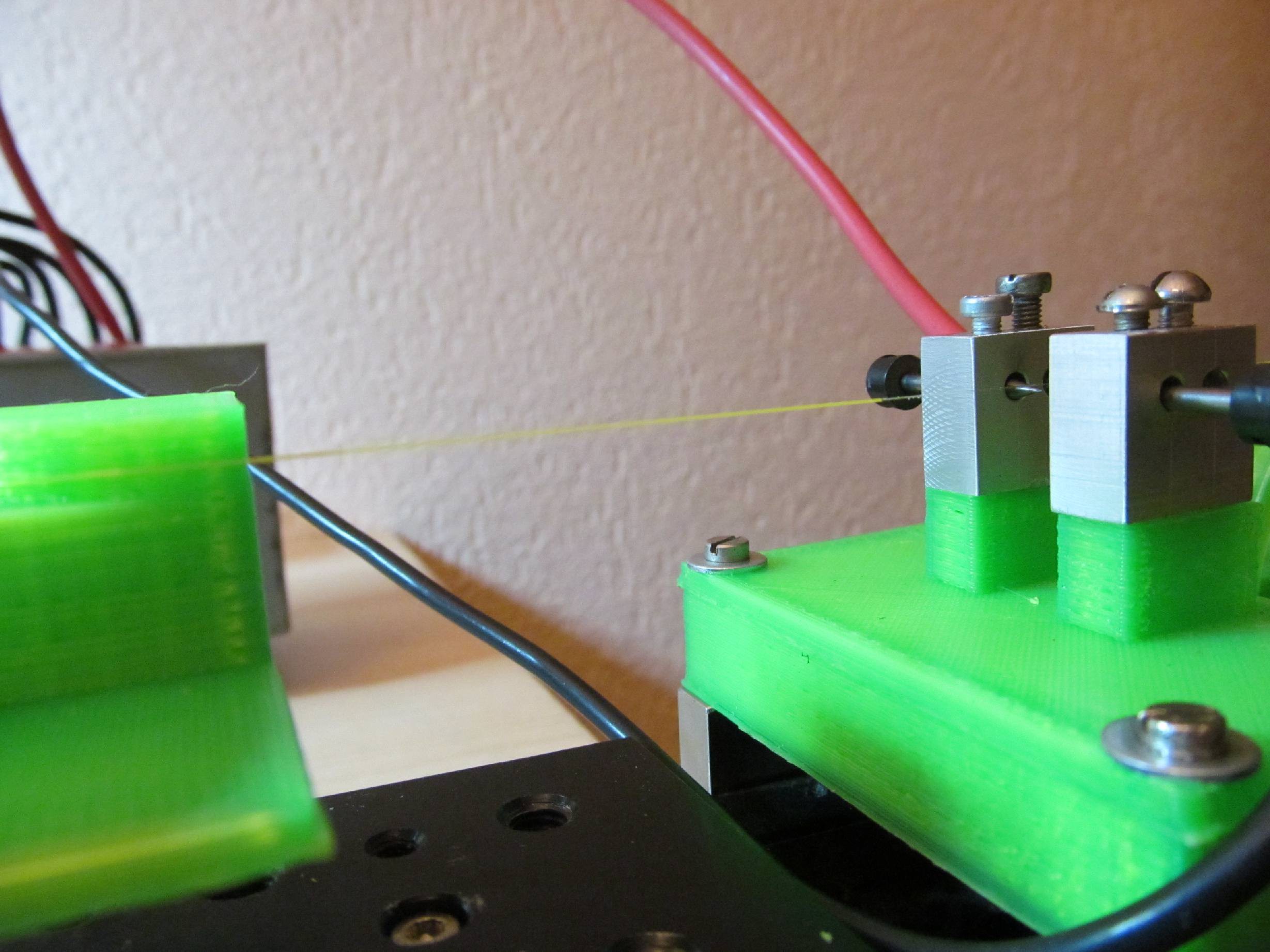
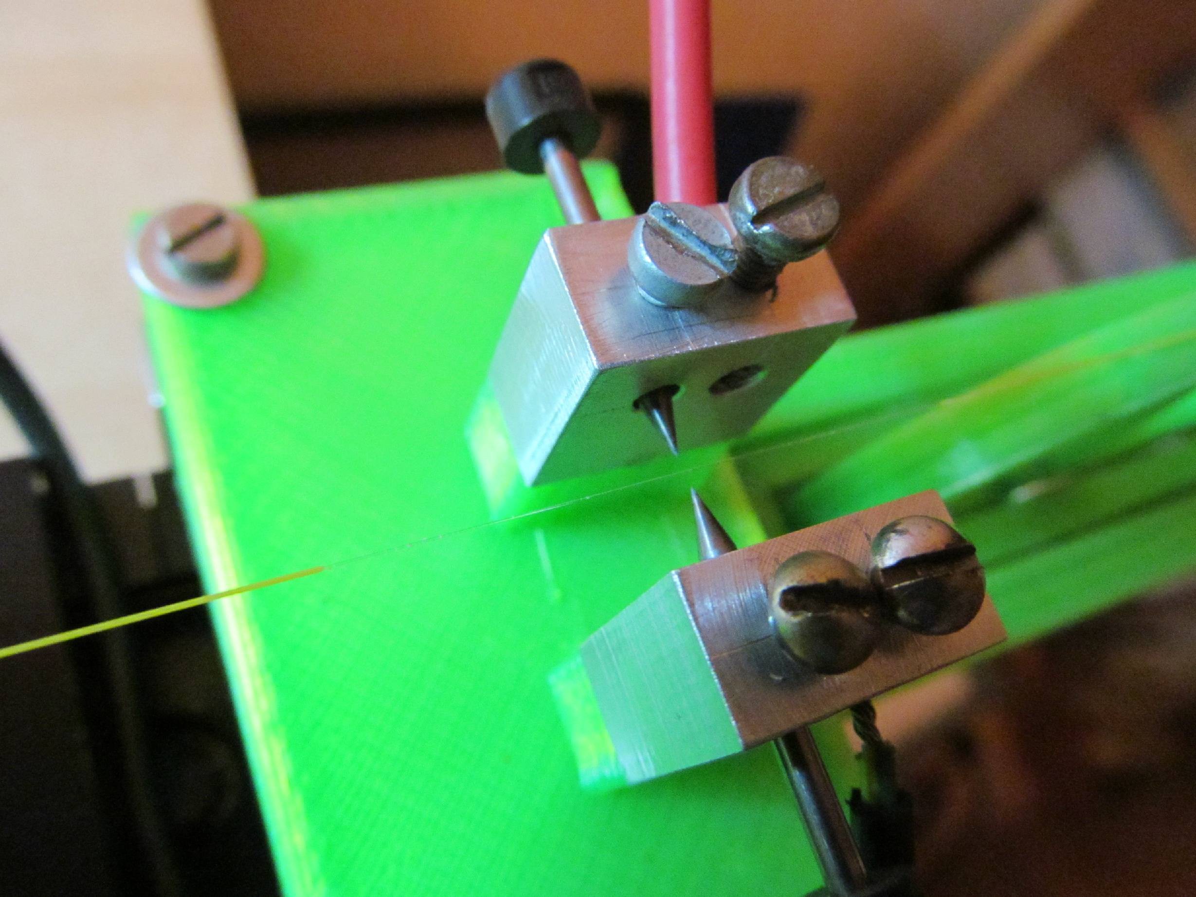
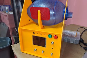
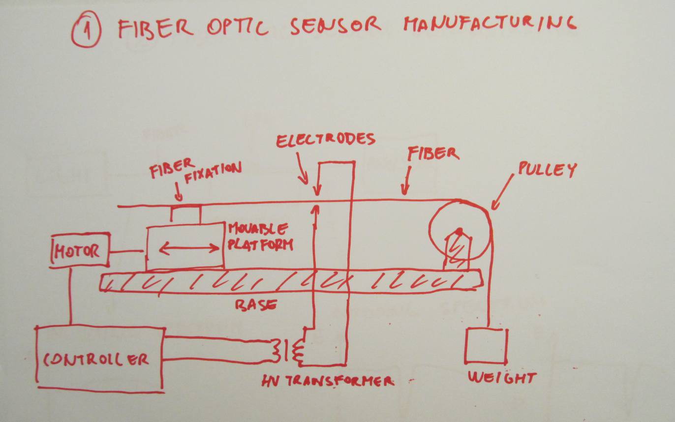 There is montor, moving movable platform on signle base. The fiber is fixed to movable platform and can move horizontally. Its second "fixation" point is pulley, fixated to base, but able to rotate freely. On the second side of fiber is small weight, pulling the fiber over the pulley and keeping it straight.
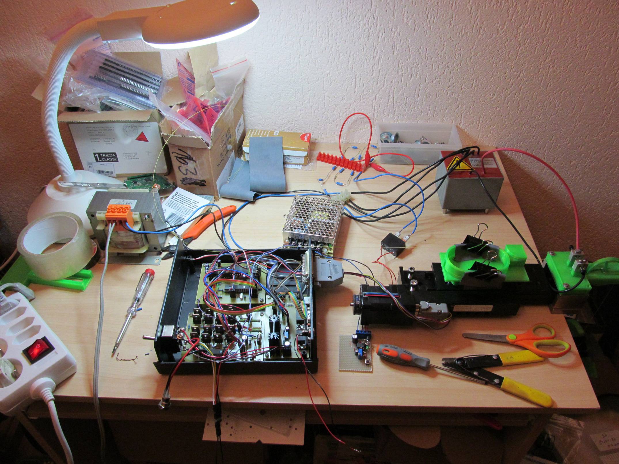
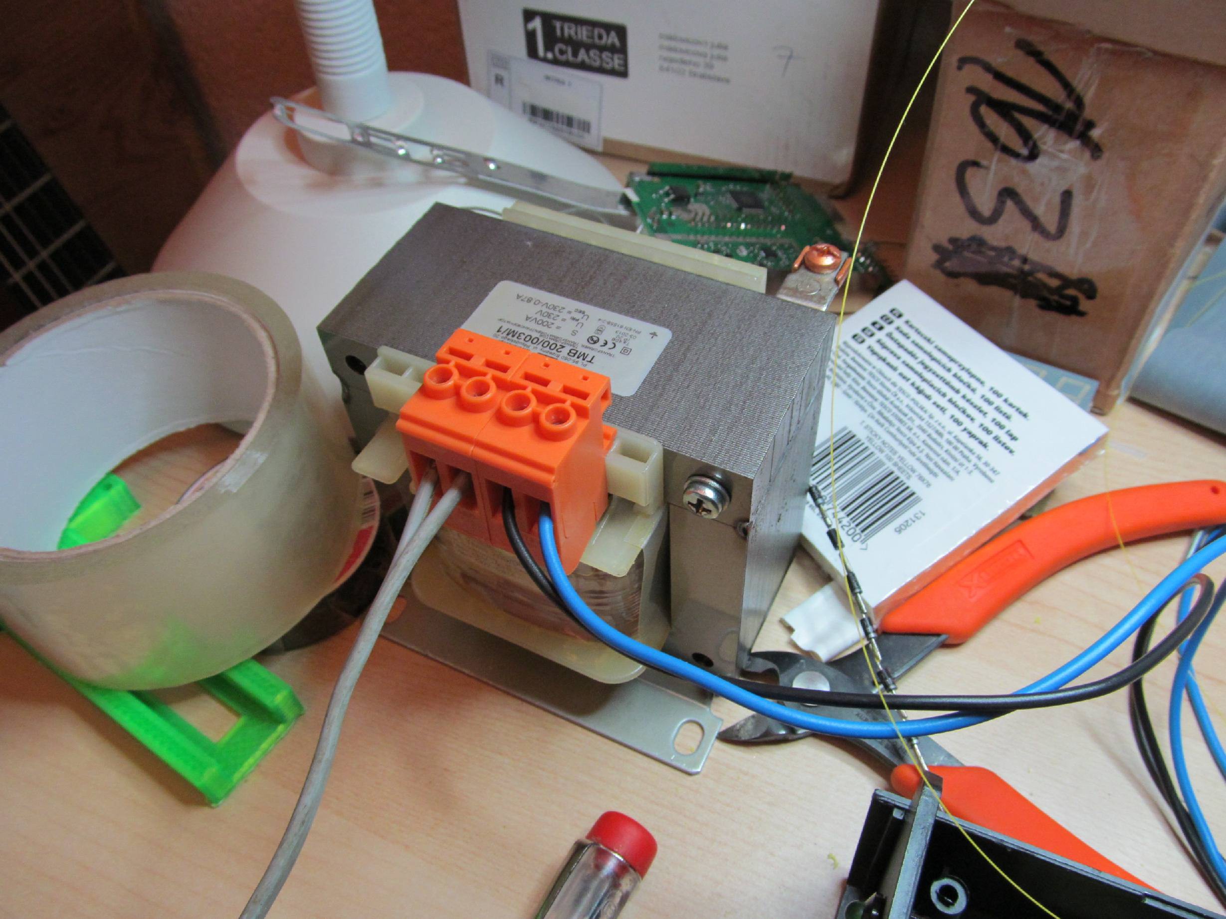
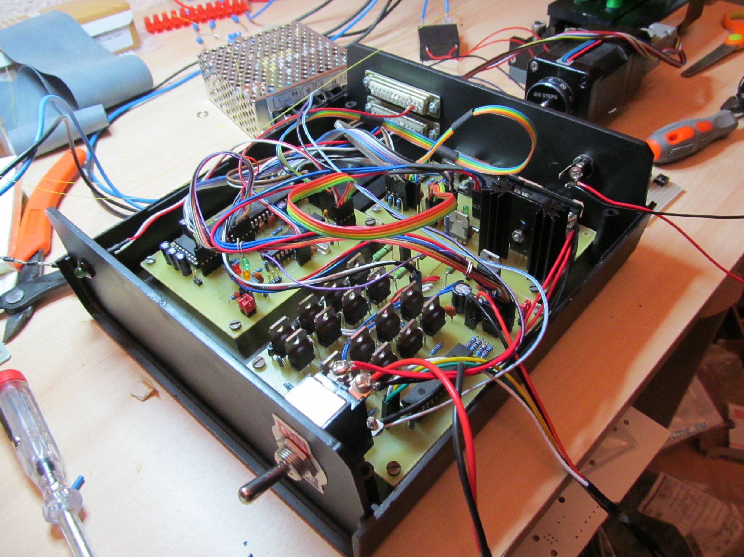
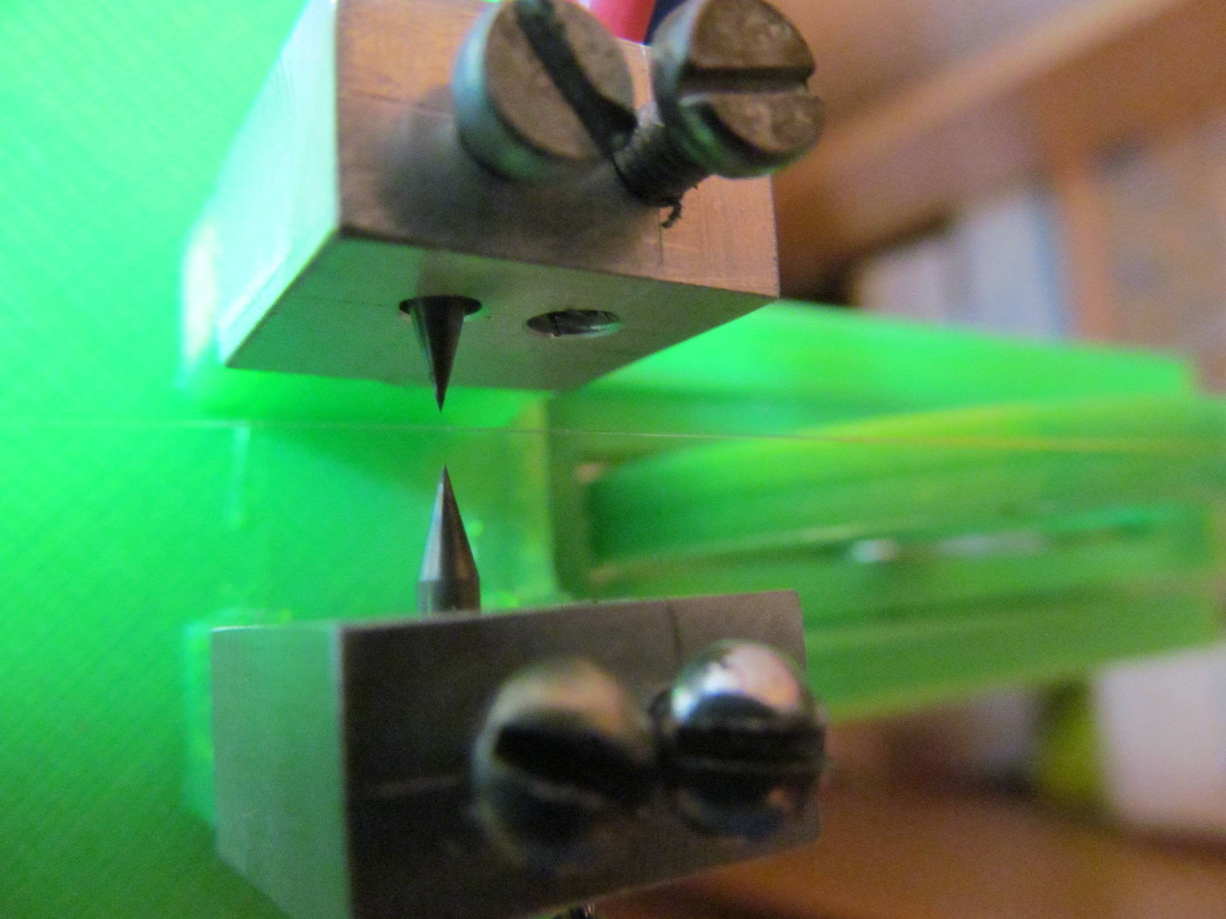
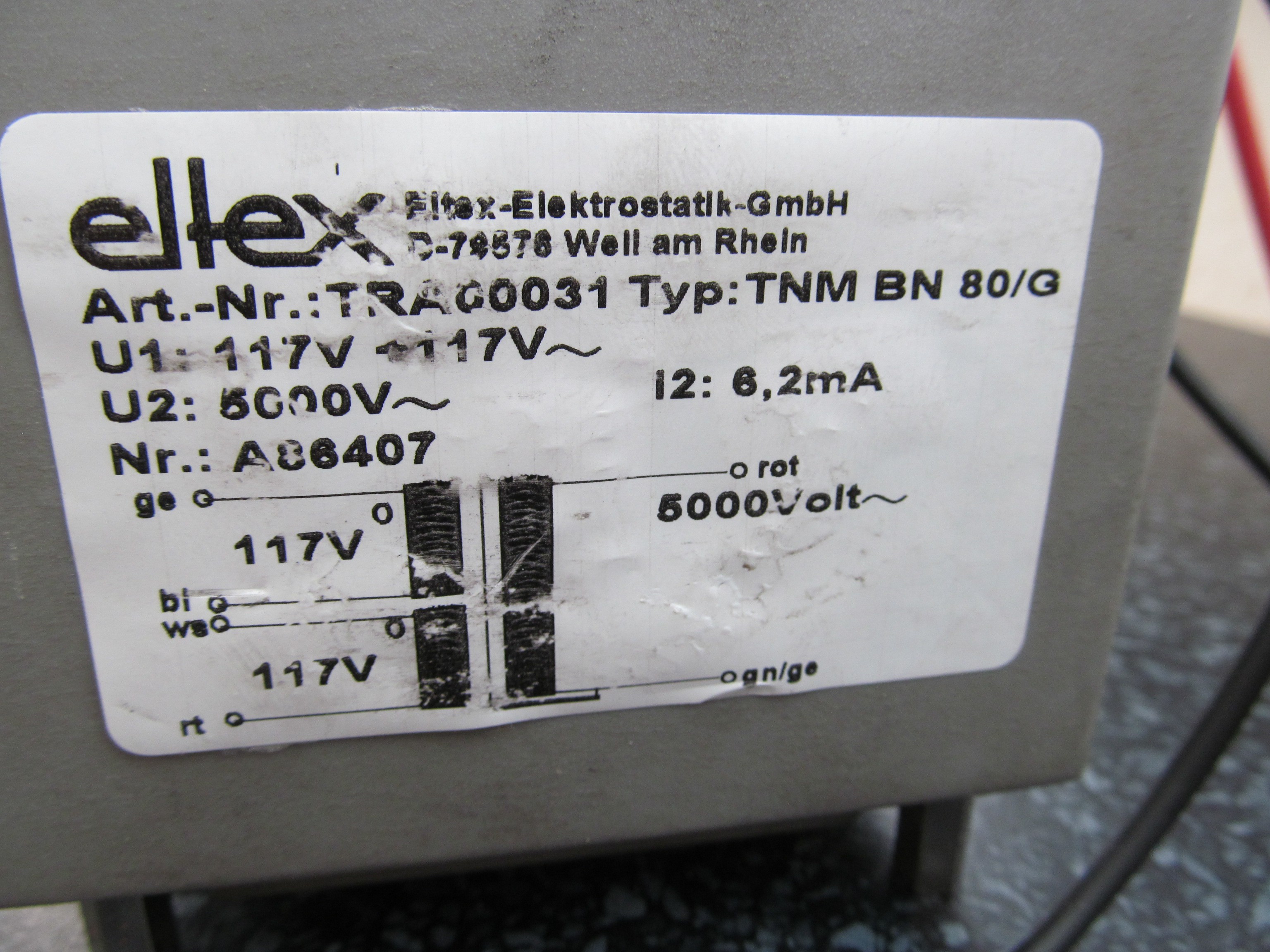
The controller is able to rotate the stepper motor in order to move movable platform, but also switch high-voltage transformer. Fiber is located between electrodes of the high voltage transformer and the heat from electric arc - formed during switching the transformer - creates desired perturbation on the fiber and long period grating consequently. After each spark the fiber is moved by stepper motor.
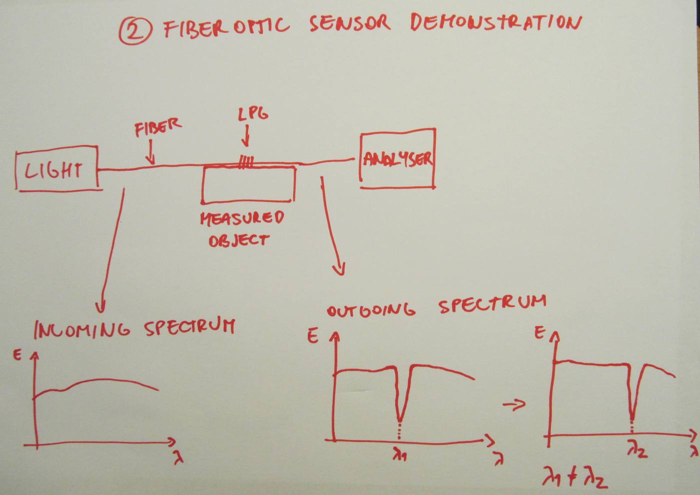
2, Spectrum analyser, to observe sensor wavelength spectrum and demonstrate its functionality
 The main part of this task is spectrum analyser in 1500nm range, so silicon photodiodes are unusable here. The details will be covered in future project logs.
Both the parts can be integrated into single device, controlling the fiber wavelength peak during inscribing.
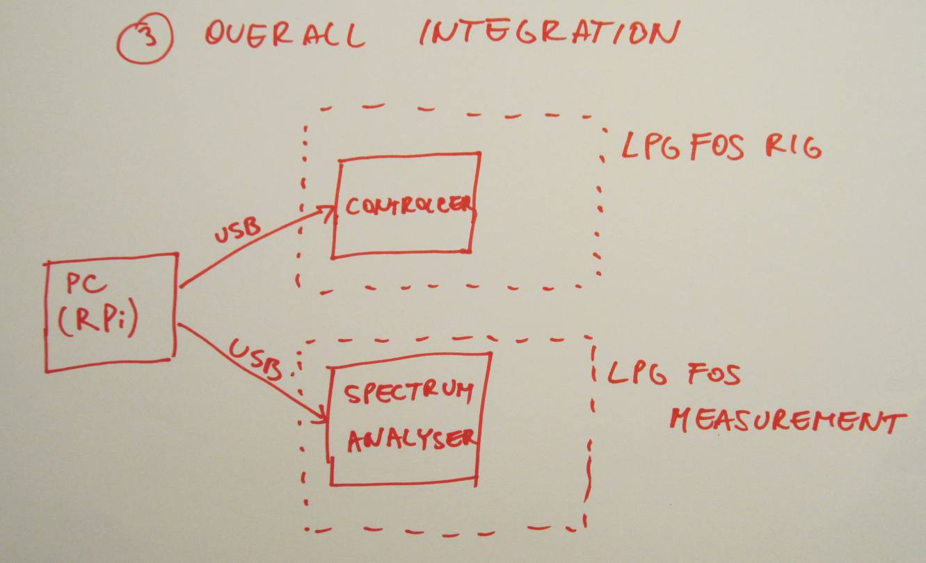 The heart of this will be computer (Raspberry Pi comes to mind), controlling both spectrum analyser and inscribing controller for fully automatic fiber sensor inscribing process through USB.
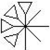
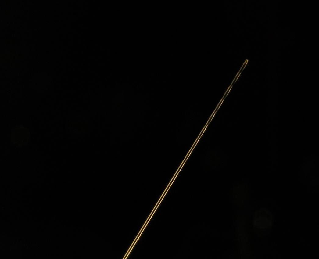 The photo of this 125um thin fiber was being shot with my Canon PowerShot SX150 IS with no special optics. Nice job for this cheap camera. You can clearly see the places at the end of fiber, periodically thinner than the rest of the untouched fiber - this should be the parts, where fiber and cladding modes meet and do a phase cancellation, as explained before.
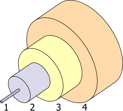 1: Optical core (outer diameter 9um), carrying the useful information.
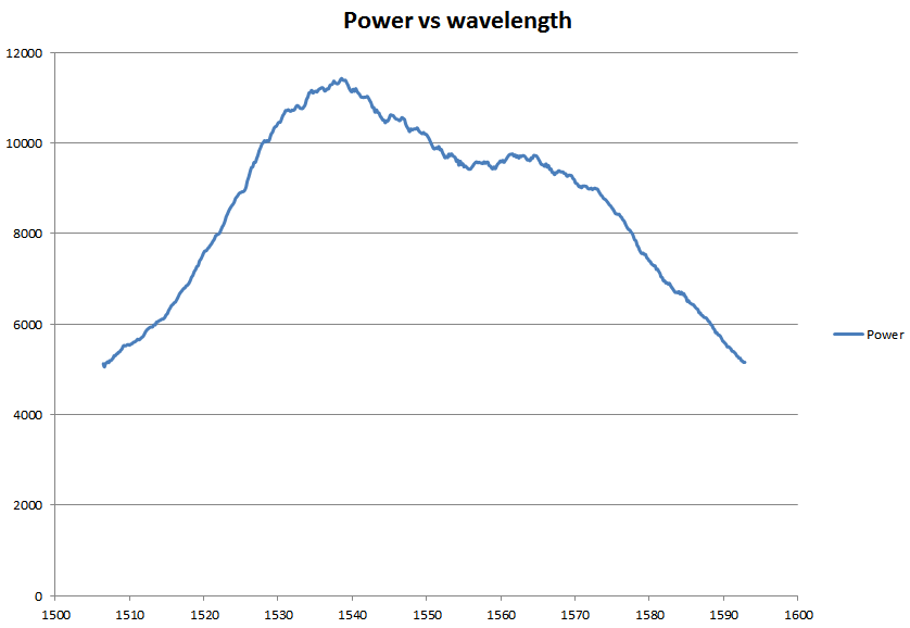
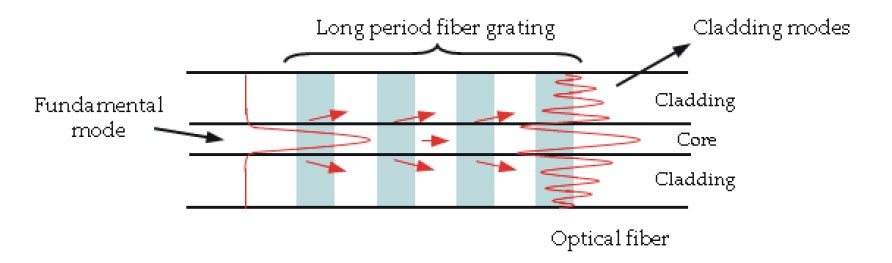 This effect increases insertion loss (=the fiber is less "opaque" for some wavelengths) at specific wavelengths. Spectral characteristics of the fiber looks like this
 If we concentrate on particual section of the spectrum, like 1480-1550nm, there is only one peak. Because the phase cancellation conditions depend on physical dimensions between perturbations (grating period), change of the grating period changes also the peak wavelength. Grating period can be changed by stressing the fiber (normal glass fiber can be elongated up to few percents with its elastic, reversible deformation), so applying mechanical strain on the fiber with LPG also changes peak wavelength accordingly (to higher wavelentgths). After releasing the strain, mechanical properties of fiber retrun to normal and peak wavelength. Reversing the observation: from the change of wavelength we can determine strain applied to sensor and this is what looks like tensometer - it actually IS tensometer! ;-)
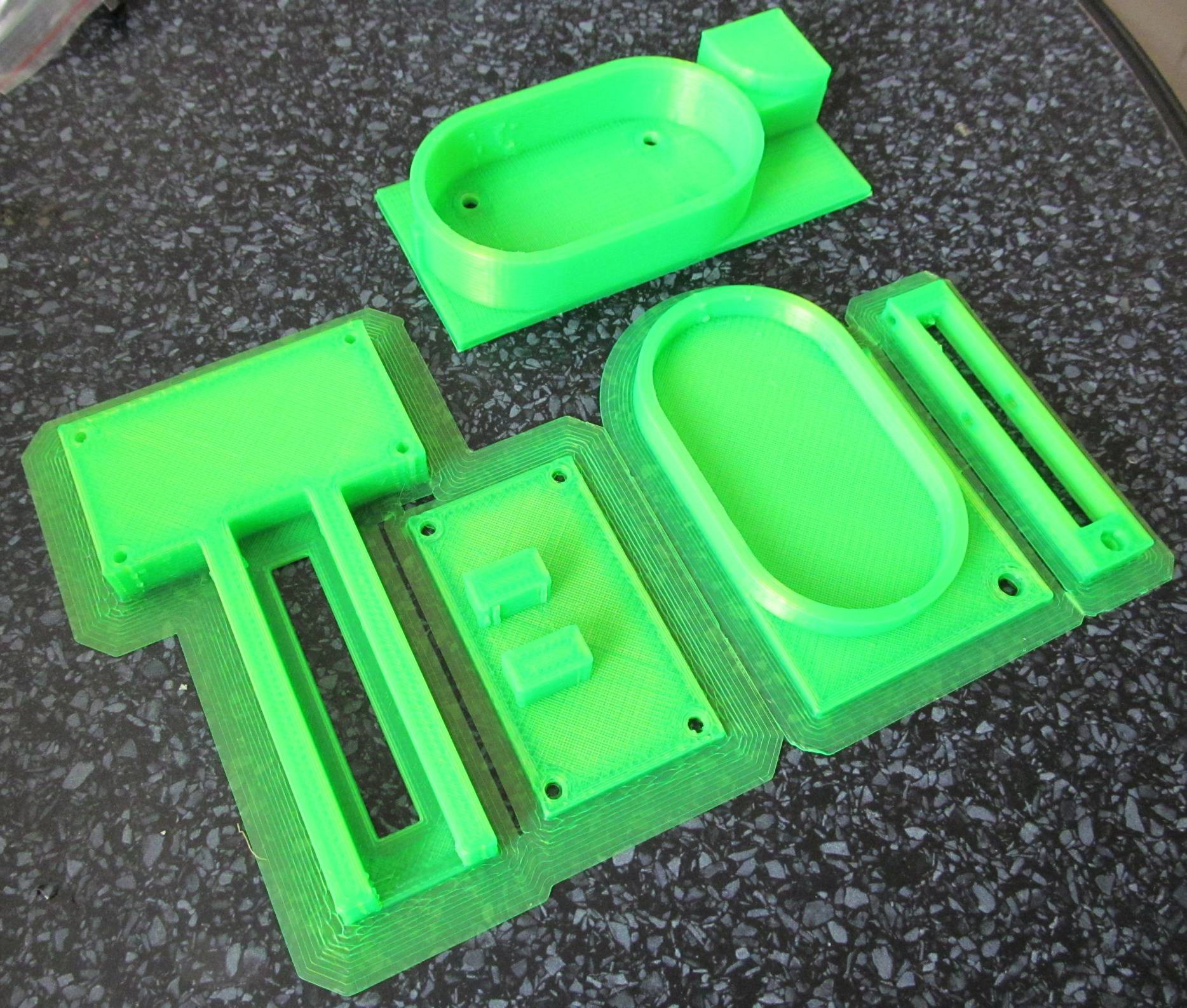


 Daren Schwenke
 Minimum Effective Dose
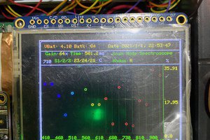
 Adam Munich
Let me tell you, this project was indeed very ambicious and is very good you had the courage to started it. You have to know, entire companies with hundred of thousands dollars of available budget are focused into this task and yet, they fail to achieve low cost fiber optic based sensors. But the technology is moving fast these years, and i am sure some technique or material would be available soon to open these alternatives in a good position to activate this technology.