 EK
EKBeginning the AFSR project was kind of confusing. It was difficult to figure out where to start. There’s many moving components in this robot. So I sketched some of the sub-assemblies onto paper. Sometimes for visibility, I skewed dimensions of the sketch to be longer.
Here is a timelapse video of the drawings being drawn.
Read more for details and ideas about the sketches!
Sketch 1
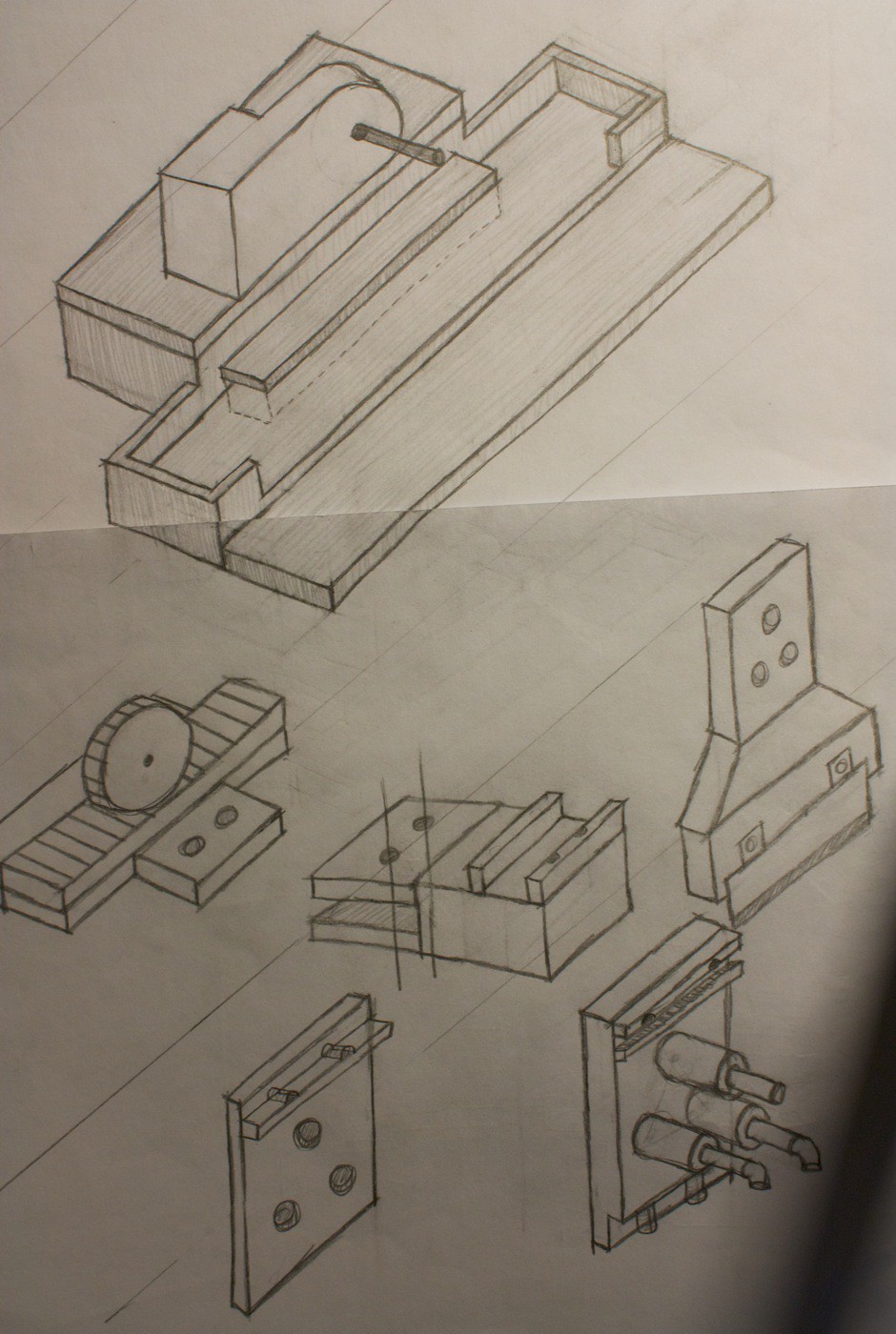
This sketch shows the Y-axis Slicer at the top, and the End Effector Attachment near the bottom of the page.
The idea with the y-axis slicer is that it will be a rack and pinion mechanism, to slide the end effector attachment back and forth. There is a tray with the y-axis slicer to make sure that the entire mechanism won’t slide out. Depending on the motor speed, the gear ratio may need to be reduced.
The end effector attachment clamps on to the main tool using three cylinders. The thought here is that the two cylinders on the bottom will be able to take most of the force from the cutting, and the cylinder on the top will be used to align the assembly together. There opposing side will ‘clip in’, and hold the tool inside of this ‘case’.
By using cylinders, I’m hoping it will be easier for easy disassembly/reassembly than it would be with a longer rectangle shape. Once you have one of the cylinders through, then find the 2nd, and then the 3rd will automatically follow. As opposed to having to angle everything and push the piece in at the same time, if it were a rectangle.
We’ll see how this all works out after testing it. It’s the first idea.
Sketch 2
This is the ‘carriage’ of the Z-axis carriage. The thought here was that the gear set will be able to be between the two sides of the racks, and move up and down.
Except that this wouldn’t actually work, because the frame would not be able to fit around the gear set.
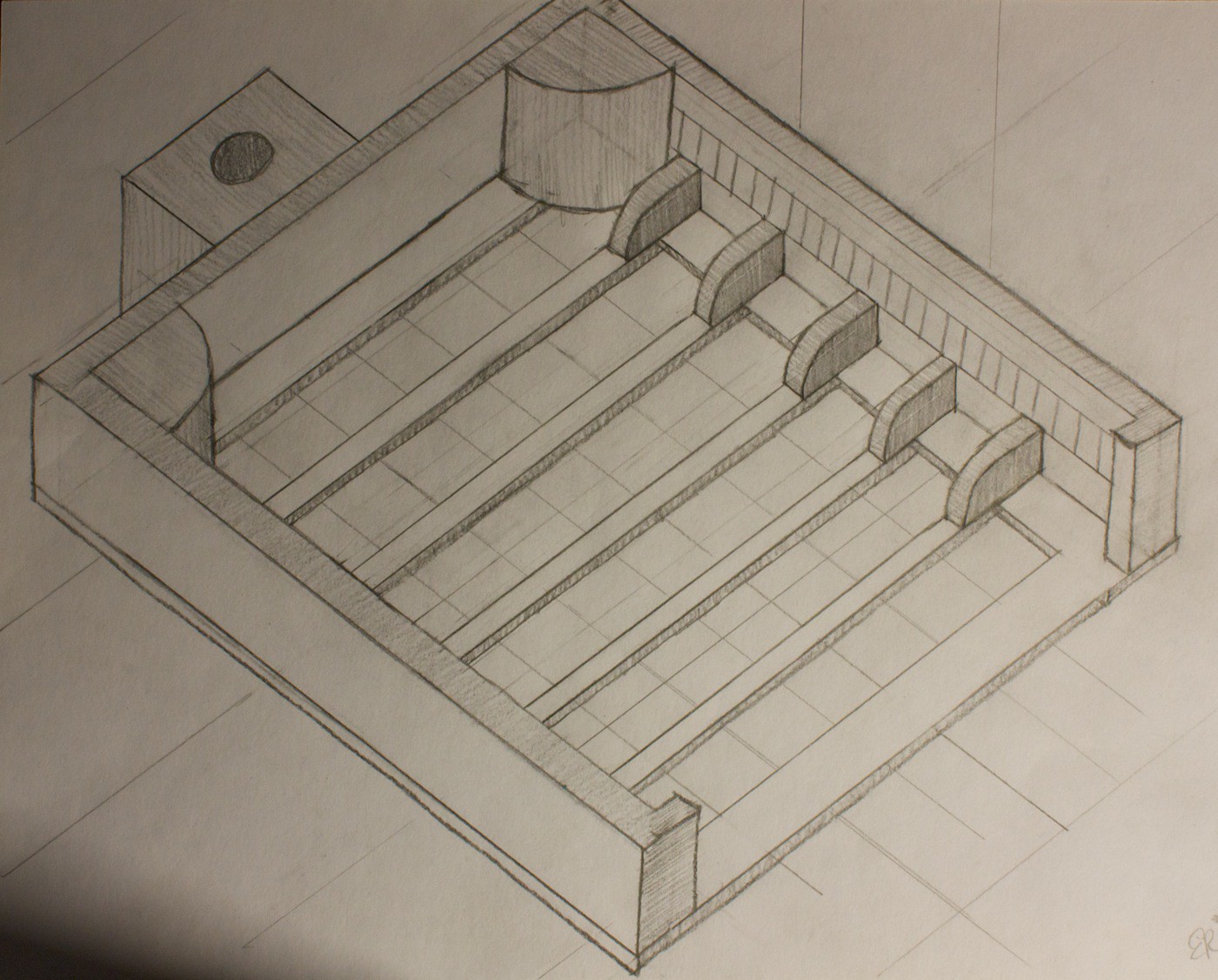
Sketch 3

Solving the fitting around the gear set problem would be easy by having the racks attach to bars, which would attach to a clip to hold it all together. Also there are now spaces for pieces of the gear set to slide along, to keep the entire assembly aligned.
Sketch 4
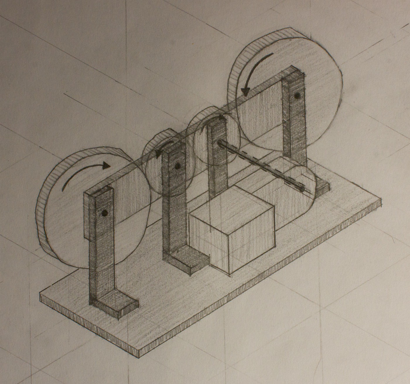
This is what the gear set would look like. Something very simple, with a small drive gear, the same size for an idler gear, and two large gears to serve as pinions.
Sketch 5
One of the aspects of this whole project I’m struggling with figuring out is how all of the sub-assemblies will attach together, and where. This is an example of the Z-Axis Carriage attaching to the Y-Axis Slicer.
This probably won’t be the best way to attach it, because it will flex upwards, and snap at the attachment point.
More brainstorming will have to be done on this. Thinking it will be easier to visualise this when the sub-assemblies are actually printed out.
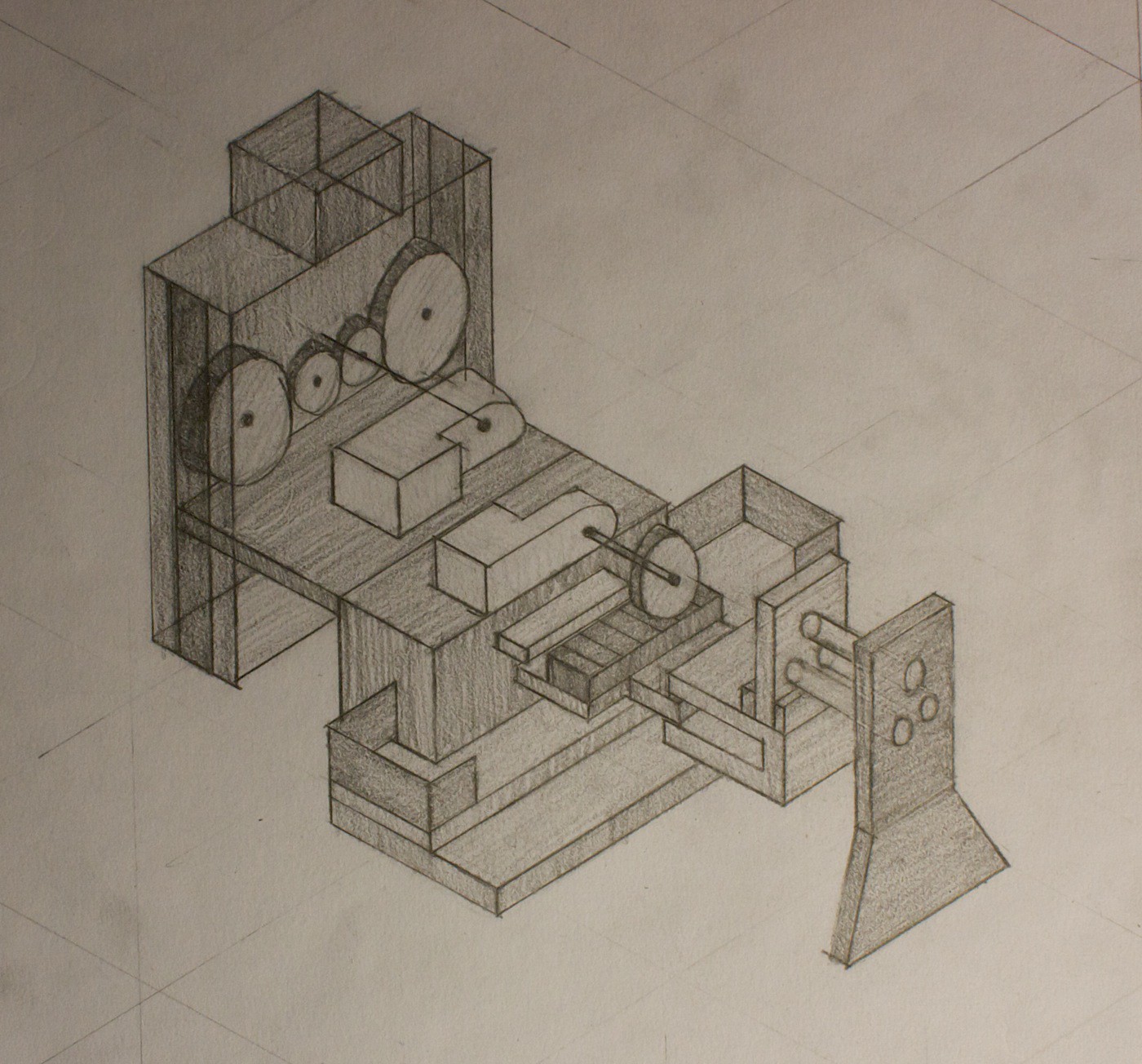
Sketch 6

This is the front view of the entire robot. It also shows the remote panel mounted on the side of the robot. Notice how there are very few buttons, and a giant e-stop button. The hope is that it will be straight forward for people to use.
The X-axis spans across the entire robot, plus some space to the left to account for the size of the gantry.
The food is resting on a removable cutting board, which is on top of a cutting table. Under the cutting table are some force sensors, then the bottom table. The force sensors will be used to weigh the food. It will also be interesting to see if they can be used as feedback for cutting, to see if the piece of food has been completely sliced to the bottom.
Sketch 7

A cropped version of the above sketch, focussing on the chassis for clarity.
The first fail of the project goes to a drawing I made where there were 3 gears in the gear set, and this gear set was attached to a rack, using the outer two gears as pinions. This doesn’t work because the two pinions wouldn’t be moving the rack in the same direction. Yeah. #FAIL. Luckily caught the error before wasting too much time on it.
My focus right now is on the Z-axis Carriage. Created a model a few days ago and printed out the first trial pieces today. Now have to analyse them and iterate on the design to make it work.
Discussions
Become a Hackaday.io Member
Create an account to leave a comment. Already have an account? Log In.
When you learn how to use a kitchen knife correctly (or any sharp blade really), you learn that you do not simply "chop" directly down with it unless you want to dull (make blunt) the blade very quickly!
Watch a few cooking shows of people cutting carrots or other vegetables, and it may appear as if they are cutting directly down, but in fact they have the tip of the blade rest down on the board and simply levering the thumb guard down (front of the grip just before the blade), and either having a thumb or their other hand pressing down on the thumb rise (top blunt side of the blade just before the handle). This allows the blade to actually "slice" through the object with it's sharpness rather than forcing it through (chopping like an axe), which will dull the blade even if it is sharp!
Another option to consider is a rotating blade, a bit like a cutting disc on a Dremel (or other rotary tool). It's constantly spinning and again, goes down slowly and allows the sharp blade to do the work rather than forcing it's way through. People generally only force through when the blade is dull and they are too lazy to sharpen it (or the object they are cutting is too strong for the blade they are using).
Now there is a major benefit in having the rotary tool option, in that you can very easily make it spin atop of sharpener, and it need only just lower itself down into the sharpener until a certain level of resistance is felt or with some other sensor. A sharpening mechanism could very easily be made for option one (first big paragraph), however you would need to add an extra mechanism to sway the blade like a guillotine through the sharpener, and it would obviously extend beyond the containment of the machine, whilst a circular blade would remain inside of the device, preventing people having to worry about sharp blades coming out of the device.
I really love your project idea, so please don't take my feedback negatively! Feel free to throw extra questions my way though if you have any :)
Are you sure? yes | no