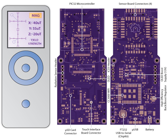
After a marathon programming session, the different modules of the software came together wonderfully for the prototype video nearly two weeks ago -- it's been very exciting to see the Arducorder Mini hardware coupled with an attractive and intuitive user interface:
Hardware Errata
I tend to think of first prototypes as a sketch -- in hardware -- that's as close to the final project as time and experience afford, but with the knowledge that for a sufficiently complex project there will always be an errata, or list of items that need to be modified or corrected in the next revision. The idea here is to make our mistakes cheaply so that everything has the best possible chance of working the first time -- and to ensure that we have enough wiggle room to tinker with any critical bits that don't work the first time, so we can quickly narrow down any design changes for the next revision.
With PCB turn times taking about two weeks, my recent focus has been revising the few issues that popped up when validating the hardware, and sending these new boards off to be made. It's my hope that if everything validates fine, that these boards will be the first official release candidate for the Arducorder Mini.

Motherboard
I confess that when I designed most of the first revision boards, I failed to include mount points on the motherboard and capacitive touch board that would allow the whole thing to be placed in an enclosure! This was a bit of an issue, since the motherboard is only 2-layers, and so densely populated that I had to increase the size a small amount (4mm in both width and height) to accommodate four M2 mounting holes. If I was willing to increase the PCB specifications to 4-layers the board would have been significantly less dense and made mounting much easier, but I'd like to keep the specifications as low as possible so that the boards can be made inexpensively, and the open source community can easily modify the designs with the free version of Eagle CAD. I remember years ago reading that when Stephen Hawking was writing A Brief History of Time, his publisher told him that his readership would be halved for every equation he placed in the book. I feel the same about open hardware -- for every barrier I place on people easily modifying the hardware -- expensive software, 4 layer boards, etc -- that it will reduce the reach by at least an order of magnitude. So I'm trying to keep it simple and accessible.
Other than mechanical considerations -- the four mounting points, and switching to a connector for the capacitive touch board itself with mounting holes -- there are a few minor schematic changes for the motherboard:
- Added I2C pullup resistors on motherboard
- Fixed VCC/GND pin swap on two sets of the PIC32 pins
- The OLED 13V booster VIN is now sourced from the 3.3V regulator instead of the battery. When sourced from the battery and the booster was disabled, the OLED 13V line would be equal to VBAT, causing a few pixels to stay on, and draining the battery a bit.
These are largely minor changes, and the technical challenge is largely in rerouting big chunks of an existing board for the modifications.

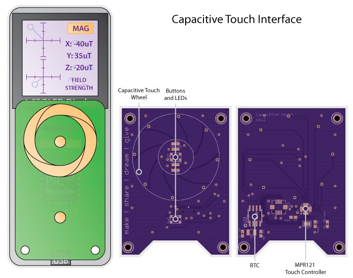
The capacitive touch wheel board also has largely mechanical modifications to allow it to securely mate with the motherboard, and to mount in a case. The parts have all been moved to the underside of the board (except for the two pushbuttons), leaving a flat surface for some acrylic to mate with for the touch wheel. I'm hoping to have the opportunity to camp out infront of the laser cutter at Xerocraft one evening in the next week or so to design an attractive case with the hardware in hand.
To help the indicator LEDs for battery charging and programming to shine through to the front face of the enclosure, I've added the small notch along the length of the bottom of the capacitive touch board. Inventables has some back-surface laser-engravable acrylic that looks very interesting, so I've ordered a few pieces and I'm excited to see what some icons for the OK/BACK buttons and indicator LEDs will look like.

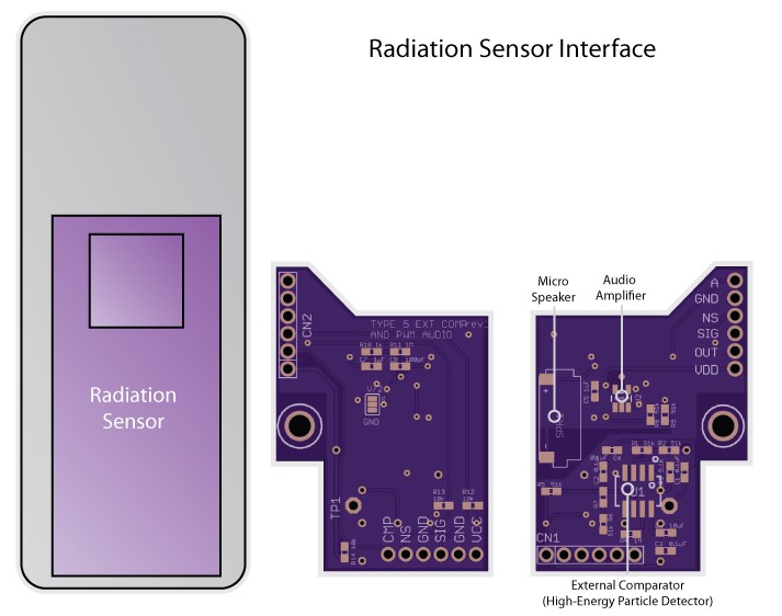
Finally, the radiation sensor backpack board also includes some minor revisions. In my rush to finish the first version of this board I forgot to include the pull-up resistors for the comparators, which I think is causing them to bounce a little on transitions (high energy particle detections). This didn't appear to be a huge issue when I was using the demo code for the Radiation Watch Type 5, but the interrupt-driven Chipkit driver that I put together for this sensor appears to be much more sensitive.
I've read that this sensor is technically capable of doing limited spectroscopy, so I've also included code in the driver that supports automatically generating pulse-width histograms that may end up being correlated with x-ray/gamma spectra -- it'll be very interesting to see these with the Cadmium 109 check source when the radiation signal has a known precision pull-up!

On a personal note, this very hungry and adorable little fellow found himself on my porch a few weeks ago, and I've nursed him back to health. Hopefully I can find him a forever home in the next week or two -- he's so young that he's still not mastered putting one foot infront of the other, and sometimes that foot lands on an Arducorder Mini!
Thanks for reading, and stay tuned!
 peter jansen
Discussions
Become a Hackaday.io Member
Create an account to leave a comment. Already have an account? Log In.
Are you sure? yes | no
Are you sure? yes | no
Are you sure? yes | no
Are you sure? yes | no
Are you sure? yes | no
say hello to kitty pls.
Are you sure? yes | no