 peter jansen
Let's have a look and see if we can figure out the project concept and begin the industrial design.
Previous Prototype Concept
Before we put together our new concept, let's have a look at some previous prototypes and see what worked really well, and what needs a bit of improvement.
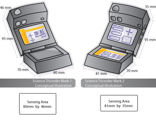
Mark 1 and Mark 2
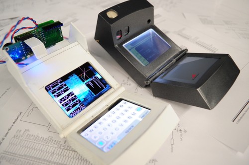
The first two models sure are cool -- they look like something straight out of Star Trek, except that they're real! That being said, they're kind of like a concept car -- super cool, but basically a nightmare to design, assemble, or manufacture. There are a bunch of flat flex cables that move power and data from the bottom of the case to the top, and these cables coiled in such a way that they'll fit while also having enough give to make sure everything closes and works properly. I've always known that this joint would be very difficult to manufacture, and a potential point of failure from all the flexing.
User interface design, visualization, and human factors analysis are (as dorky as this might sound to non-academics) hobbies of mine, and I've picked up a bit of this from colleagues, friends/other grad students, and reading groups. I think the first two models did the visualization component very well, and had lots of potential in terms of user interface design. They both used touch interfaces, with the Cirque touchpad on the Mark 1, and the dual OLED touch displays on the Mark 2.
That being said, in terms of usability the models aren't just mini computers, they're sensing tools -- and many of those sensors are directional, meaning they have to be pointed at the object of interest in order to analyze it. It often felt a little funny to point the science tricorder at something and have the screen or the interface on an odd angle, so this is something that needs a bit of work.
Pragmatically, in terms of the total amount of case area and volume devoted to sensing, this always felt a bit unbalanced -- nearly all of the sensors were contained in the very front facing outward, with 90% of the device volume devoted to the computational bits, displays, input devices, batteries, and so forth. All very cool, but I think we can do better.
The Mark 5, the most recent prototype
For a case design for the Mark 5, this is what I had been thinking -- something a bit simpler, and easier to manufacture. The whole thing is normally folded (slided?) up, as you can see in this acrylic prototype:
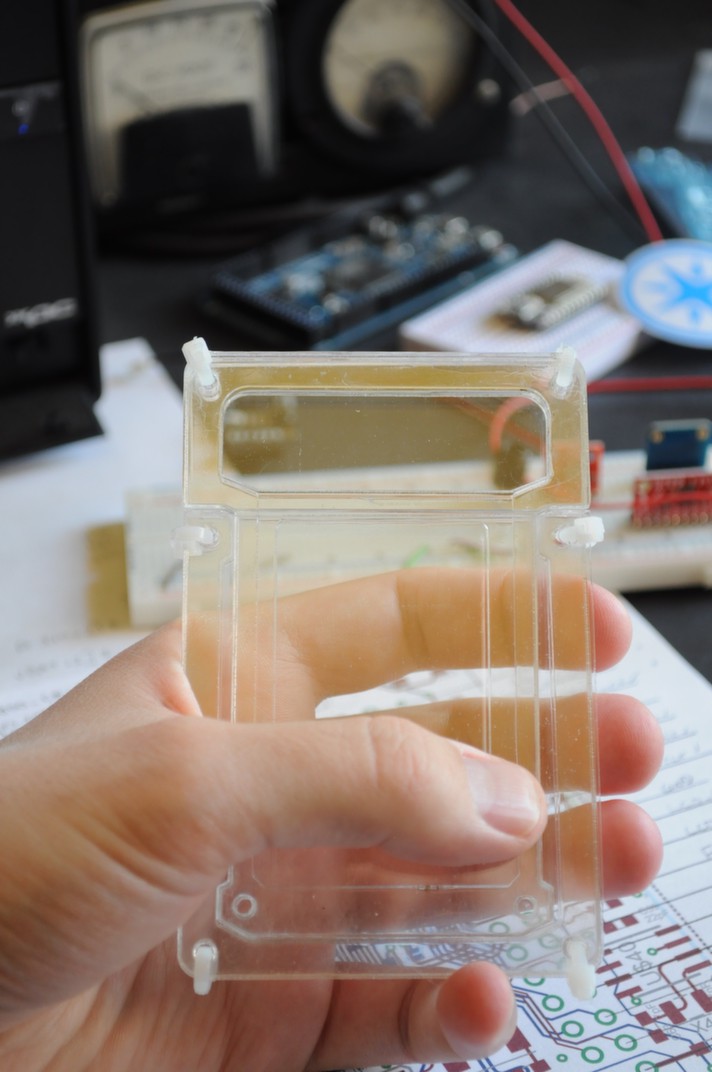
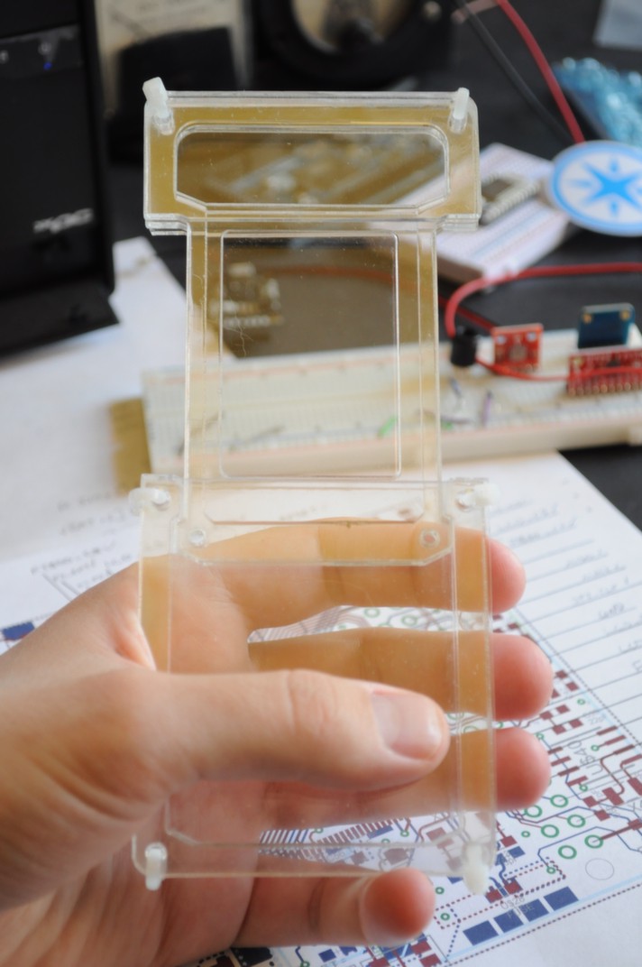
The idea being, that when you want to use it, you would click some tabs on the sides that would automatically slide the whole thing out of its shell, exposing the display, and turning it on:
There are a bunch of really exciting aspects to this design:
- More sensors: There's much more sensor real estate, in spite of having less volume. The sensors are housed at the top, and you can place sensors on both the top and bottom of the board, doubling your outside-facing sensor area.
- Robust: The screen is protected when it's not in use, which is great for kids -- they could toss it into a backpack and not really have to worry. We could also toss it into our pockets with our house keys and not have to worry about it getting scratched or damaged.
There are also a few things that make this design challenging, or could use improvement:
- Size: When unfolded and in use, it feels very large in your hand. It's basically a modern cell phone design with double the length for the case.
- Friction and Mechanics: There's a good deal of friction, and a good deal of mechanics that are involved in making something robust without wear. We don't want folks to have to take their sensing hardware to the mechanic for an oil change, or to have to include lots of expensive parts like rails and bushings, or the associated assembly cost.
But we're getting close!
Rethinking things: Designing for simplicity, usability, and tractability
First, let's have a look at some hardware constraints that'll inform how we go about our design. Many of the design choices depend on each other -- for example, if we choose a large display, we'll also need a processor that has enough RAM to have a frame buffer, or some alternate external display controller (like the FT800).
Display: The display is one of the most critical elements and the one that generally requires the most resources, so we'll start with that. It'd be nice to have something sunlight readable, which means an OLED. Unfortunately mid-range OLEDs (like the ones on the Mark 2) are generally difficult to come by, for various business reasons that display manufacturers have explained to me. This means we will either have a smaller display under 2 inches, or a much larger display on the order of 4-7 inches. Moving to a smaller display greatly simplifies the processor, graphic hardware, and battery requirements, all of which make the device much less expensive. Let's see where we can go with this.
The two largest OLED displays that I've been able to find (with manufacturing lifetimes that I'm told will extend for at least the next few years) are the following:
- ER-OLED015-1 : 1.5" OLED, 128x128 pixels, 16-bit colour. This display seems to be easy to come by, and appears to go under a bunch of different part numbers. The total frame buffer size would be 128 x 128 x 2bpp = 32k .
- UG-6028GDEBF02 : 1.7" OLED, 160x128 pixels 16-bit colour. This one seems to be a little harder to get ahold of. The total frame buffer size would be 160 x 128 x 2bpp = 41k .
Let's choose one of these, with a slight preference to the larger display if we can find an easy and reliable source.
Processor: We'll need something with at least 41k for the frame buffer, with a good amount left for processing. Ideally we'd also like something that folks can reprogram easily. I have a bunch of experience with the PIC Microcontrollers from Microchip, which generally have the highest RAM offerings of any microcontroller I've used.
The ChipKit MAX32 is a port of the Arduino platform to the PIC32 family, and makes use of a PIC32MX795F512L with 128k of RAM, 512k of flash, a zippy 80Mhz processing speed, and a fantastic set of peripherals for interfacing to sensors. The MPLAB IDE by Microchip also has one of my very favorite debuggers, so if we need to break free of the ChipKit IDE and get closer to the core for more advanced features, there are fantastic tools available. The ChipKit also interfaces the PIC32 through an FT232 USB->Serial bridge, which is a very popular and reliable chip.
Sensors: Having a smaller screen means the whole device will be much less wide, but if we're clever and use all sides/faces of the device, we should still be able to fit in a variety of sensors. The sensors that consume a lot of volume could be localized in a small area on the bottom that would allow for some height, where as the other low-profile sensors could be distributed on the sides and front of the device. Ideally these sensor boards can be swapped in and out for newer sensors or different sensing package as they become available.
Here's a candidate list, adapted from the previous open source science tricrorder prototypes:
Atmospheric
- Ambient Temperature and Humidity: Measurement Specialties HTU21D
- Ambient Pressure: Bosch Sensortec BMP180
- Multi-gas sensor: SGX-Sensortech MICS-6814
Electromagnetic
- 3-Axis Magnetometer: Honeywell HMC5883L
- Lightning sensor: AMS AS3935
- X-ray and Gamma Ray Detector: Radiation Watch Type 5
- Low-resolution thermal camera: Melexis MLX90620 16×4
- Home-built linear polarimeter: 2x TAOS TSL2561
- Colorimeter: TAOS TCS3472
- UV: Silicon Labs Si1145
- Open Mini Visible Spectrometer v1 using TAOS TSL1401CL 128-pixel detector, with NeoPixel light source
Spatial
- Inertial Measurement Unit: Invensense MPU-9150 9-axis (3-axis accelerometer, gyro, and magnetometer)
Other
- Microphone: Analog Devices ADMP401
The two main things missing here are the GPS, and the ultrasonic distance sensor. While a GPS requires about a square inch of hardware, that will just give you a set of coordinates -- in order to display maps, you need a lot more hardware. Phones already do this very well, so this might be a little out of scope (although it's still on the wishlist). The ultrasonic range finder is something that I'd love to include, but it's the largest sensor by a wide margin. I'd absolutely love a small distance detector with a range of 10 meters or so, perhaps optically based, and after the base unit is developed it'll give folks (including myself) a platform to develop and experiment with their own sensor boards and novel sensors.
Input: Because of the smaller screen and slimmer form factor, we're going to have to change from a touch screen to something different. There are two main things the user will have to do with an input device: navigate menus and options, and input text. Let's experiment with two options that fit the size profile, and see how they work. The first is a capacitive ring wheel sensor, that seem to be popular with handheld music players. Because I don't have a lot of experience with capacitive touch sensors, we'll also have a more conventional option as a backup -- a super low profile joystick.
The Muse
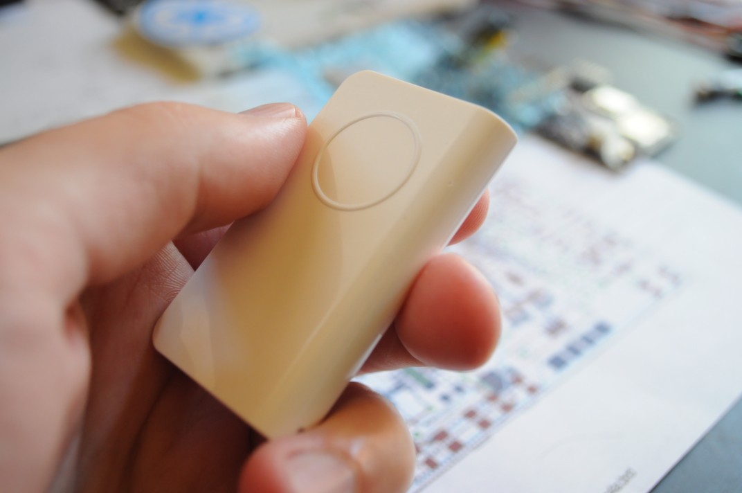
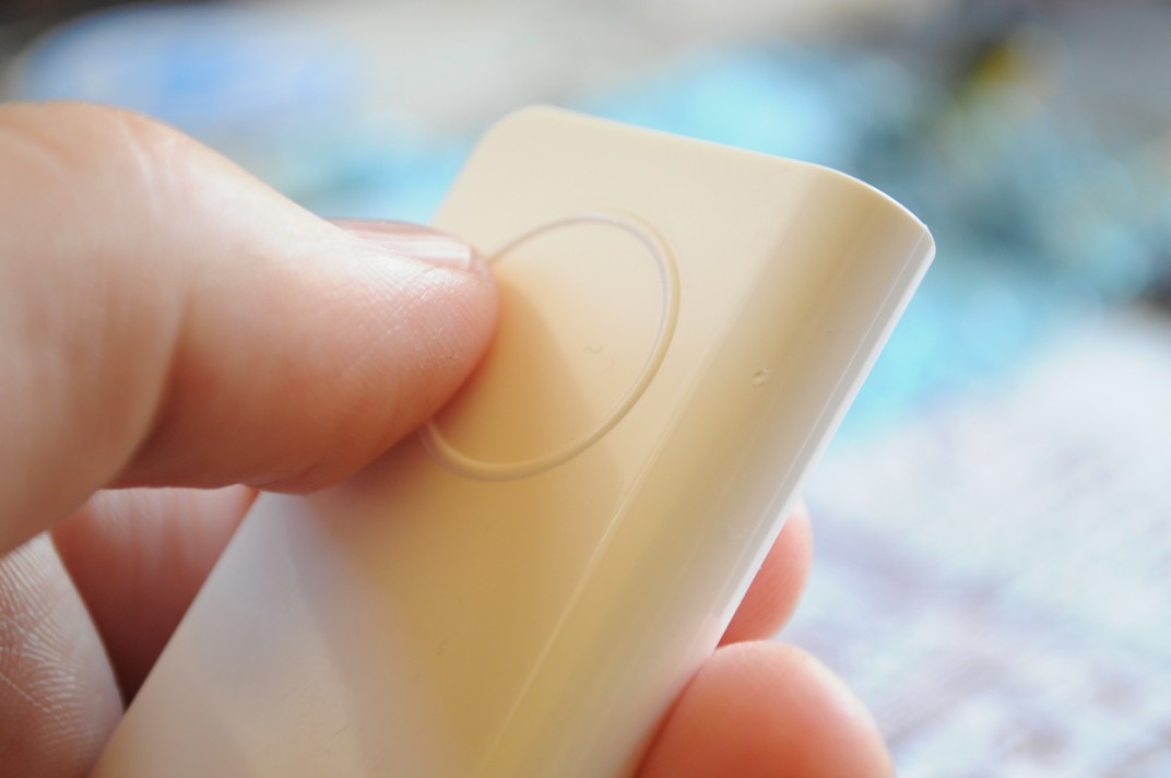
Even the best sounding idea on paper may turn out to feel or work horribly from a usability perspective. So it's great to find (or make) a model that you can hold, manipulate, and get a feel for.
After searching around, just such an item was already handy, the case for the Radiation Watch Type 5 radiation sensor. It even has a perfectly sized circle for where the ring wheel or joystick would be, and the position feels very natural. With a bit of imagination we can think of what it'd be like with a ~30mm screen sitting atop, as well as some extra bulk in the back for the sensor package, and draft up some mock ups to make sure there's enough space for everything.
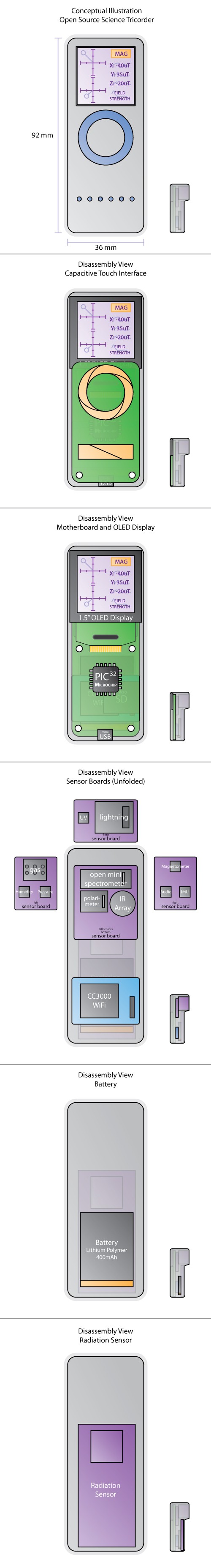
Mock Ups and Industrial Design
I put together some concept drawings for the industrial design. These are scale drawings, so in addition to describing the look and feel of the device, they're a reference for designing the shape and mechanical bits of the circuit boards.
It's important to make your mistakes cheaply, and so I've separated many of the subsystems onto separate boards. This means that if any issues crop up, we should be able to work on the rest of the project while the board house does another turn of one of the boards. I've separated the capacitive sensing board (because it may end up changing to a joystick or other input device), and the WiFi board (since I don't have a lot of experience with radio modules) from the motherboard. Four individual sensor boards -- front, bottom, and left/right side -- are also separate, for modularity.
Here's the mock up, with the different board layers exposed:
Next Steps
Many breakout boards and parts to evaluate the critical components are on their way, which is very exciting. Next up we'll do some prototyping, then layout the initial board.
Thanks for reading!
Discussions
Become a Hackaday.io Member
Create an account to leave a comment. Already have an account? Log In.