 Chad Paik
After few sessions of brainstorming and sketching the mechanical design, our group was able to create a CAD drawing of the finger portion of the exoskeleton. My (Chad) finger’s dimension were used to dimension the fingers. The CAD was designed with a table, with varying measurements for each finger, which allowed us to create 4 finger models with different dimensions (excluding the thumb) at the same time.
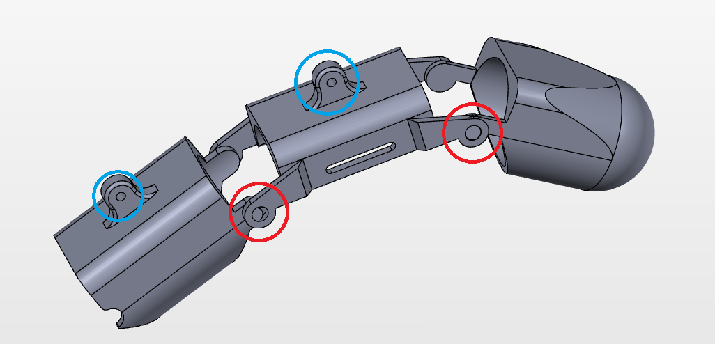
The three sections of the finger exoskeleton are connected using an outer joint (indicated by red circle below). It is using a “snapping” method to connect the sections together. This was necessary because the axis of rotation needs to be on the same part as the finger. The design that we created allowed for an “invisible” rod to go through the finger that allowed the skeleton to move like the fingers.
The two sections had connectors (indicated by blue circles below) for connecting the 4-bar linkages later on.
Below is a picture of our first finger assembly in solidworks.
Discussions
Become a Hackaday.io Member
Create an account to leave a comment. Already have an account? Log In.
One thing to note: When this finger was designed, we used a mathematical table to input all the dimensions of each finger. Therefore, when we made one part, Solidworks automatically generated 4 different parts for the other fingers. This allows for any person to just input their finger dimension and print a product fit for their size!
Are you sure? yes | no