 Beaglebreath
I will use a total of four MCP9804 temperature sensors. They will provide the temperature of the object being measured and the air temperature.
Sensors on an i2c bus have addresses to differentiate one sensor from another. The MCP9804 can be addressed by changing the wiring on three of the pin connections of the sensor's case. Applying voltage to a pin sets a bit high for the address logic in the sensor. I have designed a set of circuit boards which have set the address pins to different values for the sensor attached to the circuit board.
This table shows the name of the sensor, description of it's use and the i2c address.
| NAME | DESCRIPTION | i2c ADDRESS |
| TA | Air Temperature | 0x1c |
| M0 | Material Sensor 0 | 0x1f |
| M1 | Material Sensor 1 | 0x1e |
| M2 | Material Sensor 2 | 0x1d |
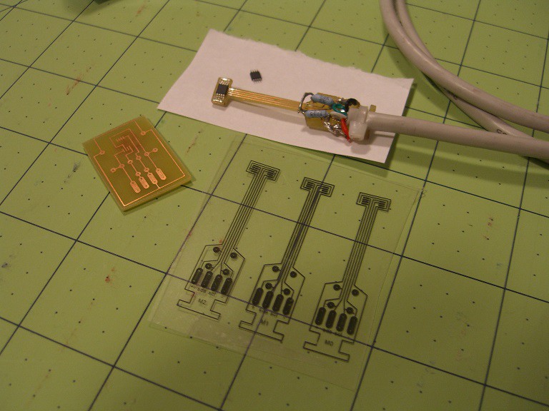
The following picture shows some of the evolution of the temperature sensor pcb design. The rectangular pcb is the first design built. This circuit layout works well for testing, but doesn't look as cool as the guitar shaped design I came up with next. However the boring rectangular design works correctly. The second design has been a failure so far.
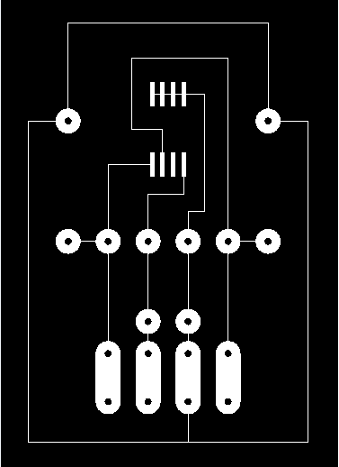
The following is an AutoCAD drawing of the original pcb. Solder pads are provided for the two pull-up resistors, a decoupling capacitor and the temperature sensor itself.
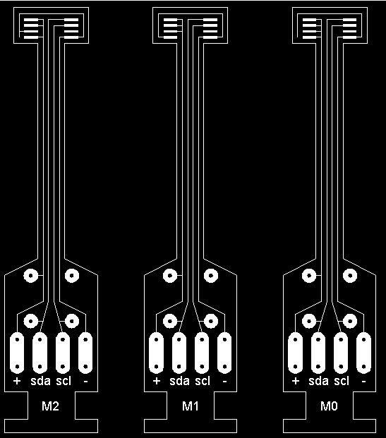
Finally, this is the next revision of the temperature sensor circuit board. it allows the sensor itself to be placed into a tighter area. The differences in the three circuit boards establishes the i2c addresses. But after etching a set of these circuit boards, and assembling the circuit, I have not been able to establish communication with the sensor.
Each of these will be wired in parallel.
Discussions
Become a Hackaday.io Member
Create an account to leave a comment. Already have an account? Log In.