 Danny
Danny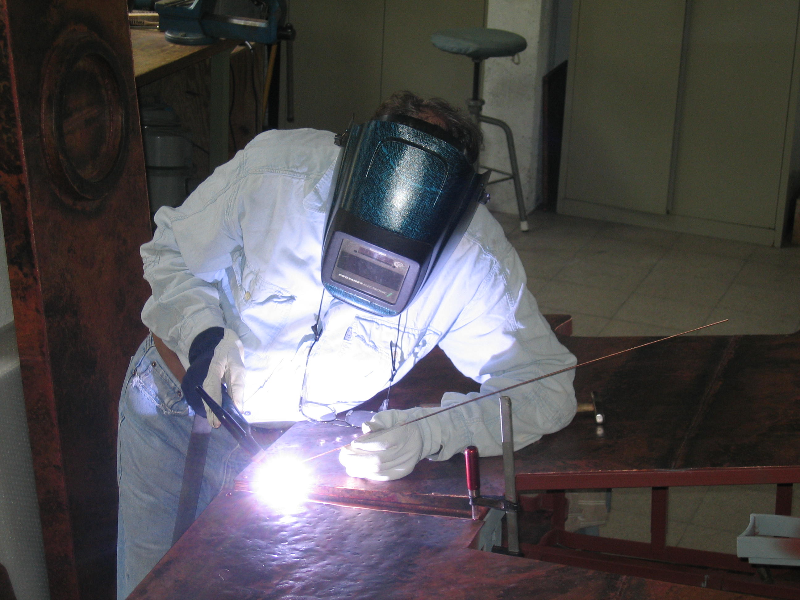
(Image attribution: From the Wikipedia article on TIG welding. Author: JoJan)
The intent of this project is to produce a robust and reliable welding current (and gas) control circuit suitable for converting an old stick welder to a TIG welder.
It is possible to get a good deal on an inverter based TIG welder, however many people find these under powered and not reliable.
Older transformed based (heavy Iron core) welding transformers provide an excellent current source, but no gas control as such are useless for TIG welding (with the exception of scratch start steel only tig welding using a torch with a manual gas valve.)
However these older transformer welders are cheap, I once found a 220A SIP branded welding transformer at a car boot sale for £10. (this was unfortunately stolen when my garage was robbed) but I have since purchased a new 250Amp welder for ~£100. lesser capacity welders are available often from supermarkets in the UK for £20 - £50, with 50 - 120Amp capacity, -enough for most light home use)
This welder project seeks to provide an alternative route to buying expensive converters, (a check on ebay reveals most converters to be ~£200 just for HVHF arc start circuits leaving gas control to manual valves on the torch body!)
I am allowing around £100 for the bill of materials. Obviously a person startnig from scratch may wish to add more to the budget for buying better components, or for any tools required to make this.
The £100 BOM does not include the welding transformer.
The intention is to produce a box capable for 250amp welders, - as that's the maximum supply current of the device I have. whilst it would usually be advisable to add in some safety margin, the 250Amps is only achievable with a 415 3 phase supply. (which I don't have), meaning my maximum welding current is ~180 Amps (using a single phase 16Amps 240volt supply (that means a large blue plug also! not a regular 3pin 13amp plug.)
-essentially the design should be large enough to cope with welding transformer that require specialist sockets to be installed, thus any welder that works from a standard UK 13amp/240v supply should be compatible with this box.
(and any 120v supply that is practical for USA)
Features:
Having complained that you only get arc start for £200, I feel that I need to shoot pretty high in terms of feature set.
Arc start - HFHV circuitry to produce a pilot arc - this ionises the air lowering the resistance making it easier to strike and maintain a welding arc
AC/DC operation. - steel can be welded with AC, but other metals require AC, where one half of the voltage cycle sprays the surface of the weld with electrons, and the visa versa on the opposing half cycle.
in practice this means that one half cycle produces heat in the welt, creating the pool of molten metal, and the other half cycle cleans impurities from the weld electronically.
Weld/clean adjust - the operator should be able to chose the balance of heat and clean (Basically, adjusting the postive / negative cycle, (e.g positive time compared to negative time in a wave diagram)
weld/clean bias - adjusting the amount of voltage/current to the positive half cycle vs. the negative half cycle (basically DC offset)
pre flow gas - the amount of gas that is allowed to flow before the welding arc is struck - the gas forms a protective barrier purging the welding area of oxygen and thus stopping the weld from oxidising
post flow gas - the amount of gas that will continue to flow after the welding arc is extinguished, meaning how much barrier to oxidisation exists whilst the weld is still hot.
Current control - the amount of current in the weld dictates the amount of heat produced in the work piece (too much current will melt it, whilst not enough will cause weak welds without enough penetration), the current should be adjustable to ensure that not too much flows into the work piece.
Pedal control - A separate control for current allowing the operator to...
Read more »


 Tron9000
 John Duffy
 Quinn
Quinn
I need a tig welder under 500? Do you offer it?