 Danny
Danny
(Image attribution: From the Wikipedia article on TIG welding. Author: JoJan)
After a lot of thinking about this project I've finally settled on a "basic" hardware implementation.
Power Source:
Essentially the power source for the project will be a welding machine, either AC or DC can be used, regardless of the actual machine used the welder output will be fed through a full wave rectifier. meaning that DC will be used inside the box. - E.g DC stays DC and just passes through the diode, AC will become DC.
This DC should be around 60v at open circuit, although voltage will sag significantly whilst welding. The internal controller that generates the necessary waveforms will use a regulated 5v supply, the welding current should not sag to less than 5v. and so the welding machine should be reasonably safe from brownout conditions, However if it appears during testing that the voltage from the welding transformer (initial power supply) can sag so low during use the the micro controller used does brown out, then the solution will be to provide a backup battery, which will be charged during "non-weld" time. and provide power at all times.
(the welding transformer I intend to use provides very large current (250 Amps) with a 40% duty cycle. lower amperages increase the duty cycle, the machine is rated near 100% for 140Amps and lower, so capacitors, which cheap compared to batteries and may have large power storage capacity may not be useful for protection against brownouts at near 100% utilisation.)
The aforementioned controller will likely be a PIC 8bit micro, though I am yet to decide on the exact model. the choice of PIC micro is based on nothing more than I have experience using it, and have a PIC Kit II programmer. Code can be easily ported to Arduino if a person has a similar "I have this and don't want to change" mentality.
The controllers main job will be to read and store the operating parameters set by the operator. Generate the waveforms appropriate as dictated by the operator, and sense what is happening at the welding electrode output in order that the parameters can be controlled via a negative feedback system.
Welding Gas:
The gas Solenoid that controls whether gas flows, and when gas flows will be controlled by the micro controller, in this way a pilot arc (HV) may be sensed and pre-gas may be applied automatically before the main welding arc is struck.
Welding arc:
The welding arc will be controlled via IGBT transistors, these are chosen for their high voltage/High current handing capabilities.
HFHV / Arc Start circuitry:
The arc start circuitry will be provided by a high voltage high power source.
This will be based on a car coil.
The micro controller will generate a high frequency square wave (5v), This will be fed into an amplifier where the voltage will be increased to 15 volts. The square wave used by the micro controller causes the magnetic field in the coil to collapse instantly generating the high voltage spark, the high frequency used ensures that there are many sparks per second, appearing as a near constant stream of Electricity forming an ionised (lower resistance) path to the work piece ensuring that the welding arc can be struck, or stays struck when AC welding.
Feedback:
Near to the welding electrode output there will be some circuitry to sense the output voltage and current of the device.
Generally whilst welding the operator will specify a current setting, this is a current limit,
The amount of current in the welding circuit controls the temperature of the welding pool. -obviously on 1/4 inch steel a lot of heat is needed to ensure adequate penetration of the weld. but trying to weld very thin 16 gague steel with the same current settings will cause the work piece to simply melt.
A rough rule of thumb for mild steel is that 30A per mm is needed.
http://www.mig-welding.co.uk/tig-calculator.htm
So it is clear that it's no good simply switching the current on and letting the welder do it's own thing. some kind of current control must be implemented.
The method that I have decided to chose (for DC welding) will be to use pulse width modulation, that is turning the welding current off when it is too high in order to limit the current flow to the work piece.
It is not possible to measure the current via inductive coupling of the DC system, therefore the welding current setting at this operation will be a percentage of the input welding current. -as the welder power supply is a welding transformer, it means that the operator can select a desired current at the transformer (usually by dial indicator attached to the shunt) and then set this converter box to 100%. current may then be reduced mid weld via use of the foot pedal.
When using AC, the current will be measured via inductive coupling (much like a clamp current meter).
current will be limitted in this AC mode be operating the IGBT transistors within the linear region of operation, limiting the output voltage will limit the output current.
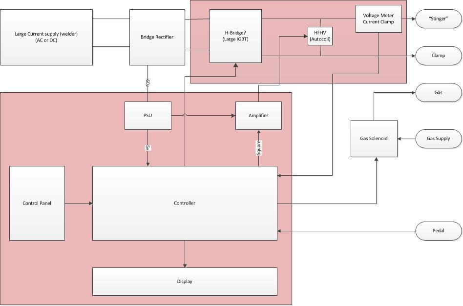
The diagram has two large red boxes. these denote where shielding should be applied.
The general world should be shielded from the HVHF arc start circuitry. and the control circuits should be shielded separately from both the HFHV and external interference.
The entire circuit should be provided in a plastic case for operator protection.
Large heat sinks will be required for both the diode bridge and the H-Bridge circuitry. Additionally fans may be used.
At the point I have an idea that active temperature monitoring may be beneficial for component protection (thermal cut out when the machine gets too hot. -but I have not fully thought this through hence it is ommitted from the diagram.)
Discussions
Become a Hackaday.io Member
Create an account to leave a comment. Already have an account? Log In.