Close
0%
0%

Reactron material transporter: OWI-535 Robotic Arm

An inexpensive robot arm retrofitted with H-bridge motor controllers and closed loop control

Similar projects worth following
There have been many OWI-535 conversions out there, this one is mine.

It uses a custom variable resistor at each joint to effectively turn each DC motor into a position-aware servomotor. It preserves the manual control mechanism, because that is a much better interface for manual commands than mouse clicks on a screen or keyboard entry. In fact, an attached computer is entirely optional.

Most importantly, it can be wirelessly controlled and coordinated with other robots or data sources.

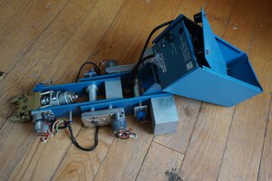
The OWI-535 Robot arm is actually an excellent bit of engineering. Made of thin-walled injection molded plastic and a handful of small DC motors, it is very inexpensive, yet is a fully functional robot arm.

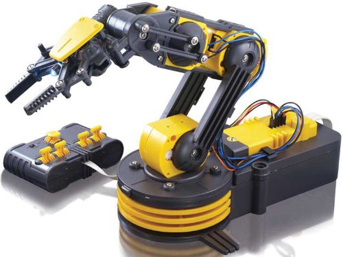
It has three main drawbacks:

  • It is a little bit underpowered
  • It is a little bit delicate in construction
  • It does not have a closed-loop control system (other than the controlling human’s sight and judgement)

The first two can be compensated for to some extent with replacement of power supply and motor management, and a small amount of reinforcement (the latter is not completely necessary, if the application is tolerant of a bit of flexure, lack of rigidity can actually be a benefit).

The third drawback can be solved by adding a control system: sensors to detect arm joint position, motor controllers to trigger the motors, and a microcontroller.

OWI makes their own USB control system which has a microcontroller and motor controller chips, but the actual “controller” is still just the human, pressing the buttons on their PC application - the closed loop sensing is the human. Any obstructions or interruptions in motion are not detected electronically. Also, since the ultimate controller is still the human, now just moved in front of the computer screen, the wired hand-held control panel is discarded, in favor of the on-screen controls.

I felt that the system could be very useful, if it was closed-loop and was able to be integrated into a coordinated computer system that used conditional logic instead of just manual human control.

I have seen other implementations, some very skillful, that have used added potentiometers, or optical encoders. Initially I considered adding potentiometers. They were preferable to me over a pulsing optical encoder because they give a sense of the absolute position without a homing procedure. Additionally, they would be tied to the actual arm position, and not the position of an internal gear that was abstracted a few levels from the actual arm position by backlash.

Ultimately I did not find any potentiometers that were suitable for what I desired. They all required bulky external mounting, or mounting that was not exactly repeatable. I was building many of these, so I did not want a one-off hot glue type installation. I wanted the same code to run on all robots, without unique compensatory constants for every single robot. Additionally, I found that the potentiometer mountings introduced another level of backlash that I wanted to avoid.

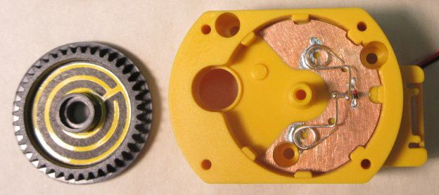
I arrived at a solution, a custom-made integrated variable resistor contained in each joint. Invisible and elegant, they did not impose any rotational restrictions or increase the device’s physical envelope.

An L9110H motor controller chip addresses each motor. The original manual control box is now wired through the microcontroller (its use is entirely optional). That allows you to drive the robot to certain positions with a very nice, physical, responsive interface, and then hit the physical “teach” button to have the microcontroller learn the position. Once learned, these positions can be run in complex sequences, in coordination with other robots.

More to come in the logs...

  • Wear in, wear out

    Kenji Larsen12/04/2014 at 04:18 0 comments

    After quite a bit of testing, I have found out a few things.

    1) there is a burn in period, where the contacts need to be worn in, before the system comes to stable values, and

    2) there is a lifetime before the values start to drift out from the previously stable values.

    This is expected, but it seems that for the materials I chose, the time to failure is too short, about 10,000 cycles. The burn in is maybe too long, 150 cycles or so. In between, the thing works very well! If I could widen the range to 0 to 10 cycles on wear in, to 100,000 cycles on wear out, I'd be happy. So it's an order of magnitude on either end. That seems doable. Perhaps not easy, but certainly not impossible. A material change could get an order of magnitude or more. I am investigating.

  • Prototype retrospective

    Kenji Larsen06/16/2014 at 03:01 0 comments

    Here is a picture of a lot of different prototypes in the development of the variable resistor contactor board.

    I say board, because it ended up being a circuit board.  But initially I was experimenting with a mechanical assembly.  Different materials, one piece, two piece, five piece, molded, machined, 3D printed.  Eventually milling a circuit board was the most elegant and reliable solution, and the only tradeoff was a small risk in contactor tracking repeatability.  That in itself is of no concern - the tolerances on the current parts are wide enough to allow for a little misalignment without any issue or loss of function.

View all 2 project logs

Enjoy this project?

Share

Discussions

Sugapes wrote 01/16/2015 at 18:21 point

Hi Kenji, great hacking! I am not sure if you are aware of it but another guy accomplished the feedback optically which should be much more robust and repeatable. Here is the link (if you don't know it already, since I believe it was featured in hackaday):

http://www.instructables.com/id/Modifications-to-Robot-Arm-for-Opto-Coupler-Feedba/?ALLSTEPS

  Are you sure? yes | no

Kenji Larsen wrote 01/21/2015 at 12:32 point

Thanks! Yes, I am aware of the optical hack, which is a very fine-quality hack indeed! I elected not to go that way because it has two main drawbacks for my purposes.

First, the optical encoder gear is the gear driven by the motor's worm gear. This gear then drives three other reduction gears and the coupling from gear to arm. These plastic parts have a large amount of backlash, so I felt that the position of a gear so far back from the actual joint position might not be accurate enough for what i wanted to do. In my setup, one side of the variable resistor is on the joint housing, the other on the arm - it is a direct measurement of the angle.

Second, the optical encoder setup counts pulses, but provides no absolute positioning information. So for that, I would have to set up some sort of homing situation, going to a known detectable reference location and then counting from there. This is a common and effective approach, but takes time. The variable resistor approach gives you absolute positioning without that procedure.

Another thing that is a combination of these two issues is that the gear assembly has an anti-gear-stripping over-torque slip mechanism, so that if the arm is stuck, the motor (and internal gears) will continue to turn, but the coupler will slip so as not to damage the assembly. Not only is there backlash in that mechanism, but if it is invoked, you lose encoder counts, and need to re-home. But then you would need a mechanism to detect that you've lost counts... This slip mechanism gets engaged if you try to pick up something too heavy for the robot, so this is a common occurrence for me. It's not just at the ends of travel for each axis, though it happens there too.

So all things considered, I went for absolute positioning referencing the outer morphology. My hack has drawbacks too, just to be fair - resistance calibration and drift over time among them. I definitely considered executing this optical hack, and who knows, this project is not done yet - I may revisit its use in the future!

  Are you sure? yes | no

Sugapes wrote 01/22/2015 at 11:25 point

Those are very good points you made. Thanks for sharing!

  Are you sure? yes | no

TJ wrote 07/25/2014 at 06:57 point
GREAT WORK!!

  Are you sure? yes | no

Kenji Larsen wrote 07/25/2014 at 20:01 point
Thanks, very much appreciated! This particular one took a LOT of iterations, and it is still being improved. Hope to post more about it soon!

  Are you sure? yes | no

Similar Projects

Does this project spark your interest?

Become a member to follow this project and never miss any updates