 SUF
SUFIn this project log I'll build the whole construction from the beginning. To understand, I started to plan this project almost a year ago, when I realized the possibility to create soldering mask at home. I don't need UV for my PCB trace manufacturing because I'm using toner transfer method for it.
The construction has the following elements:
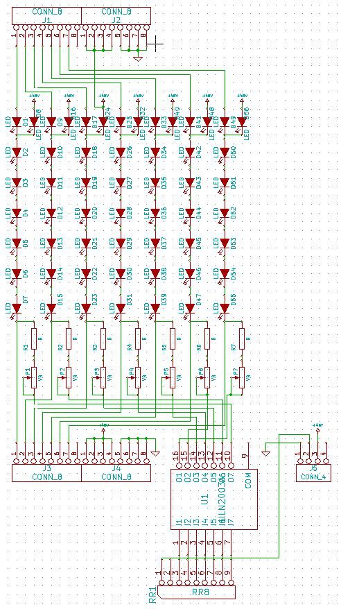
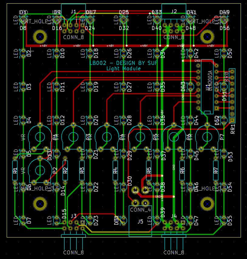
Light module: One of my major concern was, that I didn't like to etch or order a 20x30cm PCB. Etching it, drilling it is a pain. Ordering on the other has high cost. So the design is a little bit tricky. The light module become modular. I choose a 10x10cm size. Ordering 10pcs of 10x10cm board from seeedstudio cost me $25. It is affordable for this project and I use six of it to achieve the required 20x30cm size. I wanted to be able to control the current flow of the LEDs almost individually to be able to create equal current distribution. It lead me to not use parallel connection between the LEDs. Use certain amount of it in series, control the current flow of this serial lines and connect this regulated lines in parallel. This setup has the advantage to be able to equalize the current, and it has a two drawbacks: Relative high operating voltage and high number of control elements (darlington arrays and trimmers in this case). The board of the module design trick allows me to connect any number of modules in series. The module has three possible configuration:
Upper module:
Contains no control elements. The last line of LEDs are put in the board rotated by 90 degrees. This configuration connect the anode of the top LEDs together. This will be the high side of the voltage supply. This board has no connectors on the upper side.
Middle module (finally it is not in this configuration):
Same as the Top module, without the LED rotation and upper side connectors.
Low side module:
Same as the middle module, but with all of the control elements included, and the lower side module connectors are changed to the power and control connector.
Here is the schematic:
The PCB design:
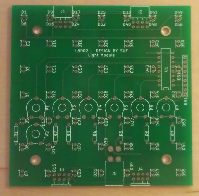
The board back from seeedstudio:
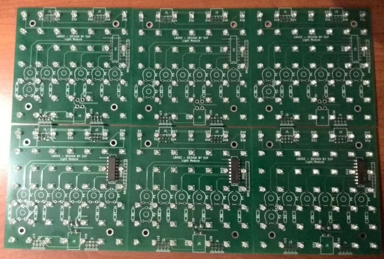
The partially populated boards (some resistors and the trimmers missing):
Discussions
Become a Hackaday.io Member
Create an account to leave a comment. Already have an account? Log In.