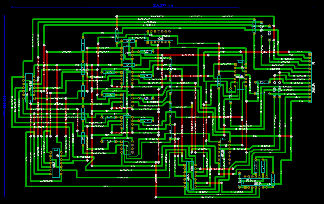
Here's a rough PCB design for the ladder divider board. I'm a prototyper, usually doing stuff on perfboard so I hadn't really ever designed a large-scale PCB like this (made a few small ones in mspaint for toner transfer) so it took a few iterations of crappy software to be mostly satisfied with KICAD. There's a few annoying things about it which I didn't find config options for, but once I got used to it the thing wasn't so bad.
This is the first draft of the PCB and it's pretty huge for only having about 12 chips and 33 resistors, but honestly there's stuff routing all over the place in the schematic. A ten-way voltage divider into stacked comparators with stacked logic outputs looping back to analog switches off the ten-way voltage divider gets pretty busy. I'll probably spend a day and see if I can improve on the design by running the divider horizontally instead of looped vertically or something. Even a horizontal loop might be able to stagger logic above and below and then more easily bus outputs to the... I don't know. Maybe.
In any case, here's a rough PCB layout theoretically optimized for through-hole single-sided board. Philosophically I should try to do everything with a through-hole single-sided board because the purpose is to do everything while dodging modern conveniences like combined logic, microcontrollers and, apparently, SMD components. Additionally if I end up making kits, through-hole is easier for n00bs to work with. Additionally if I want to prototype anything cheaply I only have single-sided copperclad to work with.
Before going too much farther I should probably consider distributing some bypass caps on the comparators and especially the op-amps and precision voltage line. Beefing up 5V and ground traces will be a good idea too. But this is a start.
Initial ladderboard PCB design
A project log for State-Based Nixie Digital Voltmeter
A digital voltmeter built without any microcontrollers or integrated ADC chips. Based entirely around discrete logic and comparator ICs.
 kittan
Discussions
Become a Hackaday.io Member
Create an account to leave a comment. Already have an account? Log In.
On the board, you still need to do a lot of optimization (I read it is a rough design, so it's okay) I've been through the same process and my counsel would be that don't rush it, leave a pair of days between each revision and you'll start seeing loops that don't need to be there, paths that are unnecesarily longer, things you can put closer together and so on.
Don't be afraid of moving things around, it's a pain in the ass, but it's well worth to explore many posibilities.
By the way, nowadays, making prototype boards is just so cheap, normally it doesn't pay off to make them oneself. (I no longer make protos at home, because between the acids, revelators, virgin boards and all the rest, it's literally cheaper to buy then prototypes made elsewhere.
Are you sure? yes | no