 kittan
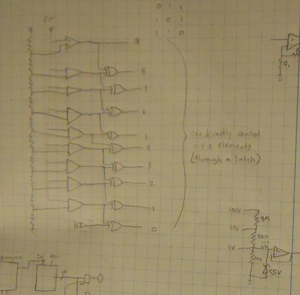
Not sure how visible the schematic is, but it's a 10-step comparator ladder. The outputs are sequentially XOR'd together such that only one output will read HIGH, corresponding to the topmost triggered comparator. This can be piped into a nixie driver to illuminate filaments respective to the measured value. If the truncated output of this were subtracted from the input (so if fed 0.865V the truncated output would be 0.8, leaving 0.065V) and amplified by 10 (so, 0.65V) the result could be fed into another ladder for the same process on the next decimal down. 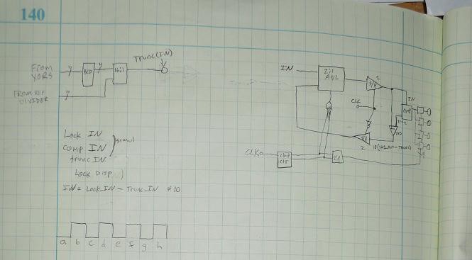
If one could latch the nixie display and increment to the next display, latch the residue for the next iteration and pipe it back in, you could build a sequential state machine with only one comparator/logic ladder that iterates residues through and latches the measured values to respective tubes on each step. The only real concern with this design is the lock/unlock timings for the sample-and-hold circuits, because if they don't trigger in the proper order you'll end up feeding next-decade-residues back into the current-decade input and hosing up the measurement.
Probably what I'll do initially is design a decade ladder with residue amplifier output. That board could be used for either the state machine or the multi-ladder design. I'll probably build the multi-ladder design first, even though the component count is much higher, because it's pretty simple repeated steps. There's a lot going on in the state machine.
Discussions
Become a Hackaday.io Member
Create an account to leave a comment. Already have an account? Log In.