 kittan
So there exists the IN-15A and IN-15B nixie tubes, which are a pair of tubes designed for meters. The IN15A outputs unit scalars like +, -, u, m, k, M and the like. The IN-15B displays unit symbols W, F, Hz, H, V, S, A and an omega. So now I'm challenged to design entirely analog meters for all of these units. If I stick to my as-designed voltmeter as a base, all I need to do is conjure up entirely analog means of translating every unit into voltage, in a completely linear manner. Most of these were pretty straightforward but also pretty entertaining. I will leave out voltage measure because it's already described in the comparator-ladder section so that's taken care of. The rest we'll see what I got.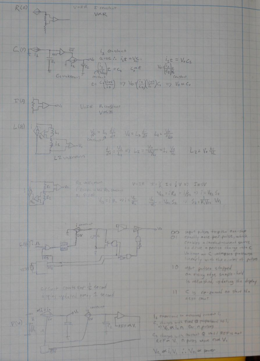
First, resistance. A constant current is driven through the unknown resistor. Since V=IR, if I is constant, V ~ R. Done.
Second, capacitance. This one gave me some fits. Use a constant current source to charge the unknown capacitor up to a threshold value. Since the voltage across a capacitor increases linearly with a constant current, the time required to charge the unknown capacitor to the preset value is directly proportional to the value of the capacitor. it=VC -> (i/V)t = C and if i and V are constant, t ~ C.
At the same time - and for the same duration - we charge a second, known capacitor with a second constant-current source. The capacitance and current are constant in this case. it=VC -> V=(i/C)t so we have a voltage proportional to the time. Since the charge time is the same for both capacitors, and the output voltage is proportional to the time is proportional to the unknown capacitance, V ~ C. Done.
Third, current. Run the current through a small fixed resistance and measure the voltage drop across it. Since V=IR, if R is constant, V ~ I. Done.
Fourth, inductance. This one was also fun, and I'm not sure how well it'll work. For a nonsaturated inductor, V=Ldi/dt. If we push current through the unknown inductor in series with a known inductor such that we maintain a constant voltage across the known inductor, we have a constant di/dt. di/di = V1/L1
A constant di/dt should induce a constant voltage across the known inductor. V2 = L2di/dt so V2 = L2(V1/L1) so V ~ L. This will only work for short current pulses because in DC the inductors will saturate, so some timing logic will be required but in general, Done.
Fifth, conductance (siemens). This is basically the inverse of resistance, so one way to do it is calculate resistance and then invert it. But that's a division step which, in purely analog circuits, usually requires a log transform, subtraction, and antilog transform. Which is difficult and hard to keep precise. So instead we'll do something different. Starting with ohm's law V=IR -> V/R=I, and knowing S=1/R, I=SV. We run a current source through a known resistor R1 and unknown resistor R2, where the current source is keyed to maintain the voltage across R2 at a constant known value. We then measure the voltage across the known resistor R1. S2Vr2=i, and Vr1=iR1 -> i=Vr1/R1 so S2Vr2=Vr1/R1 -> S2=Vr1(1/R1Vr2) and since R1 and Vr2 are known constants, S ~ V. Done.
Sixth, frequency. This one was pretty tricky. The obvious solution is to use a binary counter with a fixed duration during which to sample pulses, and an analog DAC in the form of a weighted summing amplifier. The problem with this is philosophical - it's heavily logic-based and not really an analog measure at all. Additionally, many ICs are required and the DAC might have precision issues? So we thought of something else, in the form of a state machine. The initial state is really what matters most, the rest is just there to make sure the input and output values are latched properly. So, here goes. We use a precision 32.768KHz RTC oscillator divided down into a 1-second timebase. This will have exactly 50% duty cycle, so a high pulse duration of exactly one half second. We AND this half-second pulse with the incoming measured pulsetrain and use that to trigger a one-shot with a fixed pulse duration of, say, 800uS. This is based on the maximum frequency directly measurable being 1KHz (other higher ranges achieved by decade dividers). Every incoming pulse will generate a single constant-duration 800uS pulse which will enable a constant-current source to charge a fixed capacitor. This results in fixed-duration fixed-current pulses charging the capacitor, which means bursts of constant charge resulting in a piecewise-linear increase in capacitor voltage. When the half-second gating pulse is over, we now have a capacitor C which has received nQ charge, where Q is i*800uS and n is the number of incoming pulses. Now we're seeing nQ=VC -> V=nQ/C and since Q/C is constant, and since n is pulses per half-second (f/2), V ~ f. Done.
Seventh, power. I really wasn't sure how to do this without log multiplication, which as noted above, sucks. However, I might have figured it out. First, a modification to the diagram needs to be mentioned - instead of the EN line feeding back to a pulse generator, pretend it's going straight into both current sources. Now we're ready to break it down. First we require three probes, to measure voltage V1 and current I1 simultaneously. We charge a known capacitor C2 with a constant current source I3 until its voltage reaches a threshold proportional to V1. Q=VC and since I = dQ/dt, if I is constant then Q=It so I3t~V1C. Since I3 and C are constant, V1~(I3/C)t -> t~V1
At the same time, and for the same length of time, we charge a second known capacitor C1 with a current source proportional to the measured current value I1. Q=VC so (kI1)t=Vc1C1 and since t~V1, I1V1~Vc1C1 and since C1 is constant, I1V1~Vc1 so V ~ I1V1 so V ~ Power. Done.
Well, that was all quite fun and will require quite a bit of algebra and calibration to make any of it actually useful. We'll start with making the voltage measurement and display work first, and thet move up in complexity probably starting with current measurement. Hopefully I can get this thing done sometime this year.
Additional Function Extensions
A project log for State-Based Nixie Digital Voltmeter
A digital voltmeter built without any microcontrollers or integrated ADC chips. Based entirely around discrete logic and comparator ICs.
Discussions
Become a Hackaday.io Member
Create an account to leave a comment. Already have an account? Log In.