 kittan
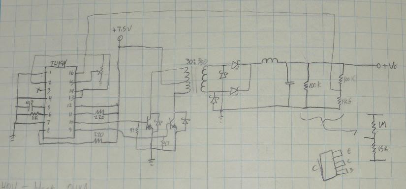
Tail-end of last year we were working on a nixie tube clock project. It ended up getting stalled by some other stuff, but while Novak was working on the microcontroller code I was grinding out a power supply and drive circuits. For drive circuitry we started out with a Russian-made TTL logic chip made for driving nixie tubes from a BCD input, which turned out to not have enough voltage clamping (if any, some versions of the chip didn't have internal zeners) to actually work with our tubes. I ended up specking a SOT-23 NPN with Vcemax of 200V, more than enough to hold off our 150V nixie tubes with no external components needed. The Vcesat wasn't so great, but since each tube would only be pushing between 1 and 4 milliamps the power dissipation wasn't really a problem.
The more fun part was figuring out how to get a reliable source of 150VDC efficiently. I hadn't worked directly with switching power supplies except conceptually and disassemblingly so I had to work in iterations. I wanted to use a push-pull topology because I wanted a transformer-based design to get the x20-x30 voltage multiplication we'd be needing, and push-pull is my favorite forward converter topology. I could have used a simple boost converter but extreme voltage changes make for crappy duty cycles which makes for lower efficiency.
The workhorse of a lot of good push-pull converters is the TL494, which integrates an RC oscillator, dual error amplifiers and two undedicated (open-collector open-emitter) BJT outputs which can be configured to operate in parallel or alternating. Push-pull requires alternating outputs. I basically set up the drive transistors as approximately Darlington with some external NPN drivers better at handling high current and voltage, directly toggling the dual primary on my transformer. Schottky diodes provide current paths for the primary coils just in case. One thing to note with the push-pull topology is the drive voltage is delivered to the center tap, so when one side is driven to ground autotransformer effects pull the other side to 2Vct; in the case of our design parameters the center was at 7.5V so the BJT drivers had to handle at least 15V. Not difficult, but in higher-voltage applications the handling voltage can get pretty serious.
I originally designed the secondary as center-tapped with a two-diode full-wave rectifier using some 200V schottkys. I somehow forgot, though, that when one side is conducting the other side is holding twice the voltage (because it's 180 degrees out of phase, so it gets the entire Vpp) and my 200V diodes were roasting from reverse 300V, which was shorting out the secondary and smoking my drive transistors. I rebuilt the transformer with a single secondary and used a bridge rectifier, so instead of 300Vpp I had 150Vpp and could use the parts I already had. Reworking the transformer also gave me chance to respool the primary with a slightly more favorable turns ratio that could allow the controller to operate at a lower duty cycle for nominal power (for a push-pull, 25% is about optimal). I think I ended up with something like 15+15:330 for a 22:1 ratio, making it easy to get from 7.5V to 150V output.
Not sure where the numbers are anymore (for some reason I must have recorded the data on a computer instead of directly into my notebook, which is atypical) but I rigged up an active load and tested efficiency up to well past 25mA (I do have numbers for up to 20mA), which the maximum draw from one of the tubes we're using was 4.2mA at 150V. I was seeing between 82% and 85% efficiency between nominal and excessive loads, which I thought was pretty good. In any case the maximum draw from the seven tubes this meter will use shouldn't exceed 29.4mA (it likely won't exceed 25 but to be safe, worst-case 4.2mA x 7 tubes) the DC supply designed for the clock should be plenty sufficient for the voltmeter. I'm not sure what my DC rail voltage will be yet, the electronics will require 5V but I'll probably have an unregulated ~12V to feed the nixie supply which will mean I'll be operating at really low duty cycle and it'd be able to provide a lot more current if I needed it.
Discussions
Become a Hackaday.io Member
Create an account to leave a comment. Already have an account? Log In.