 Kenji Larsen
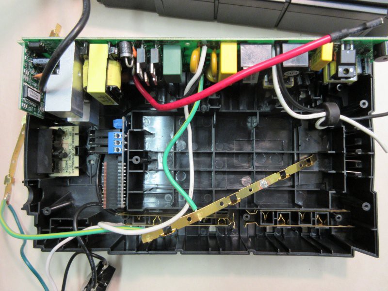
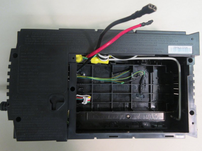
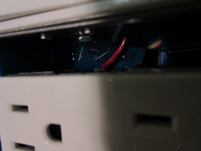
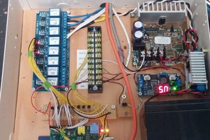
This is a wirelessly controlled UPS with control over individual power ports. It integrates into the wireless Reactron network for intelligent control. In the image below we see the original UPS board at the top, and an additional relay board in the space just left of center. This board has three sold state relays, each tied to a different power port, and allows battery backed up power to flow (or not). The board takes a standardized Reactron board with ATMega328P and HopeRF transceiver to allow remote wireless control, In this image, the Reactron board is the reddish board seen on edge, below and to the left of the three-port blue connector.
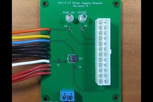
Here is a closeup of the relay board:
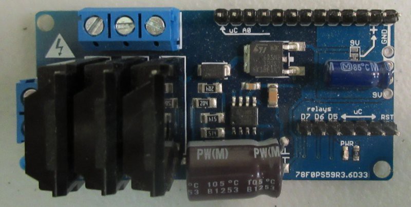
The headers on the right hand side are where the microcontroller board attaches.
As an example of usage, consider a CNC mill undergoing some sort of undesired operation. Cutting all power to all components at once may result in machine damage, or may create new, unsafe conditions. It may be best to cut all positioning motor movements first, then the spindle, then the computer controller, then the flying vision system, then the dust collection.
If an end mill is traversing through a material but there is a problem, if all power is cut at once, the end mill may shatter (complete with flying shards), the spindle may be bent, gantry misalignments ensue, etc. It is better to shut the gantry motors down first, so that the tool position comes to a halt before spinning down the end mill. It is better to have a cutting tool be able to cut through the material a short distance than to try to fight its way through with sheer pressure. Once the positioning motors are shut down, the spindle may follow immediately, then the controller computer may be shut down, then other supporting equipment, to remove all electricity from the machine enclosure in the case of emergency. The sequence may take only a fraction of a second, but it avoids tool and material shard projectiles from uncontrolled emergency shutdown. It is preferable not to exacerbate an emergency condition by compounding it.
Secondarily, it also may prevent machine damage and the costs associated with downtime and parts replacement.
Wireless control means that any conditions warranting power shutdown can come from a complex variety of sources, such as an external system processing verbal commands, an energy-conscious system monitoring power consumption in idle times of connected devices, or a remote system manually controlling the power state. The microcontroller on the UPS is resilient to power failure, and will be able to transmit the state of the power ports back to any requesting system. (“Did I leave the oven on?”, one hour after leaving the house… “No, you did not.” OK good, now I can relax. Or, “Yes you did” - OK then, shut it down now.)
A lot of possibilities exist with just a simple controllable power gate, as one unit in a larger system. One may use voice control to stop a machine in an emergency or other condition, from wherever one may be in the room... or from anywhere on the earth, where an input to the control network exists. On its own, it is still useful, and may be controlled via web page for simple remote control.
More details to come in the logs...

 Dave's Dev Lab
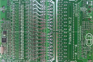
 Adam L. Humphreys
 Yonghan