 Kenji Larsen
Here are some photographs of a recently completed build.
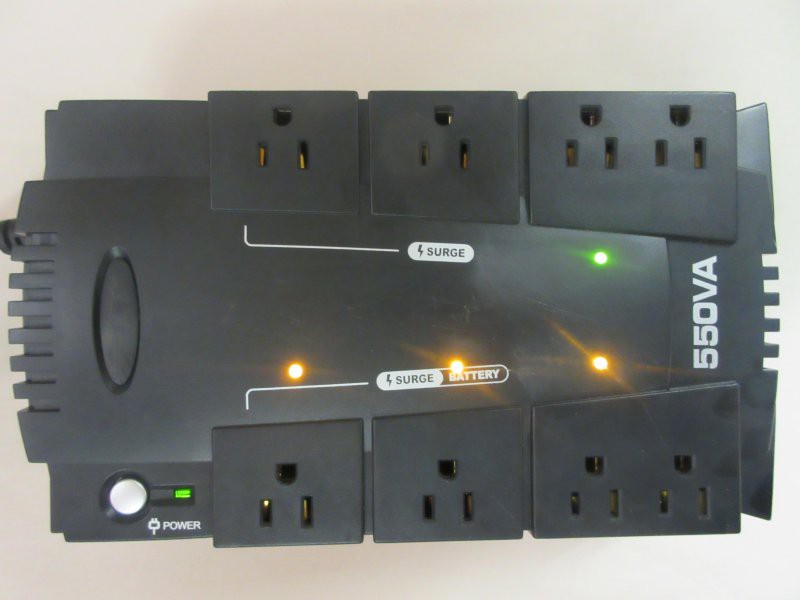
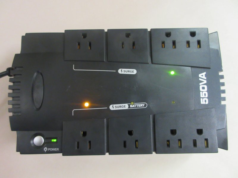
In this one, I added LED indicators to the switched outlets.
I did this because sometimes something is not working as expected, and I actually go over and stick mulitmeter probes into the sockets in question. (Is it plugged in? I start there - sometimes, it is actually that simple!) But as I was writing up this recent build, I realized, that really is silly - the same digital output that triggers the solid state relays can also handle a tiny amount of extra current to light up an LED. Then I know what is happening with the microcontroller visually and directly, without having to query its RF interface to ask it what state it is in (or thinks it is in). Sure, maybe the SSR fried or something, but >99% of the time, whatever is wrong has nothing to do with the actual power transmission working properly. So for that great proportion of the time, these LEDs will work out just fine, and can be seen from across the room. It's a simple time saver, and that is what all of this is about.
What you see in the image are three yellow lights, and one green one.
The green LED is drawing current from a digital output pin not tied to an SSR. I just make the microcontroller turn it on, when it initializes, so I know there is power and the code is running. The pair of outlets it is matched with is a "generally on" set of outlets, UPS power as per the original UPS design. This power drives the microcontroller and the relays, so if the light is not on, none of the lights will be on (unless something is very wrong, which would be great to know, too). If there is no light, there is probably no mains power. Or the microcontroller or relay board (which has the AC to DC power supply for the microcontroller) is fried. So far that has not happened. Anyway, I can still use the original LED next to the power button to indicate the UPS is functioning, and there should be power to that outlet set.
The three yellow lights are matched to two single outlets and a pair of outlets ganged together. These are the SSR-switchable outlets. The LED, when lit, indicates that the digital input to the SSR is high, and the SSR should be passing AC.
The two outlets at the top are not-switched, not-UPS protected outlets that are just surge protected mains outlets.
To add the LEDs, I soldered resistors inline and heat shrunk them, so that the different colors could just be plugged into the microprocessor's 3.3V output.
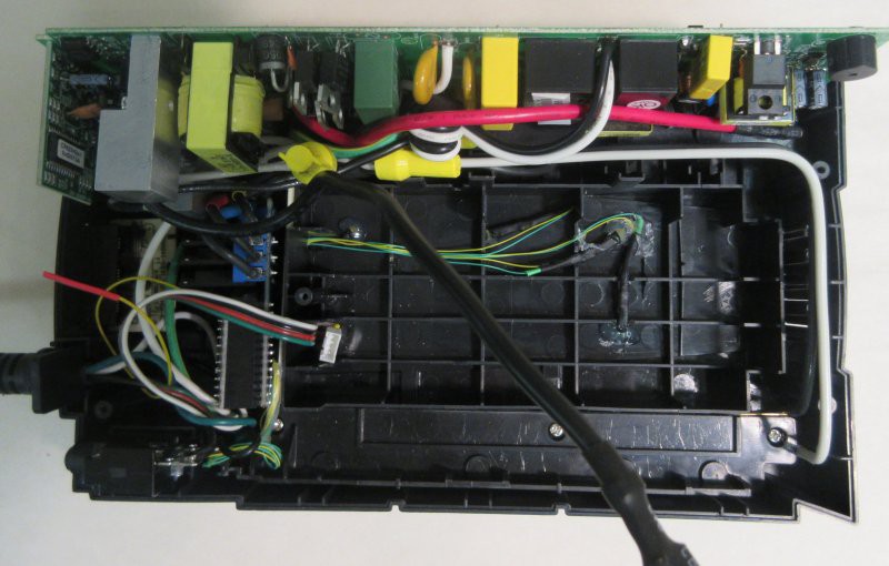
I drilled some 3mm holes and simply hot glued them in from the back. Fortunately, the manufacturer of this UPS left me about a quarter inch of space under the battery. I took a sharp knife and carved out some reliefs in some of the ribs to route the wires. Also visible in the above picture is the 4 conductor programming header wire, which I snake out into the battery compartment. I sometimes need to re-flash the chip with updates, and my implementation of wireless programming is still being refined. The loop of yellow wire that terminates in red heat shrink tube is the antenna for the HopeRF radio.

On the back of the relay board I just soldered the LED wires to the 4 digital output pins. There is a bit of clear heat shrink tubing on the cluster of wires to protect them from the header points, which might be bumpy, and as these units get moved around a lot, will help insulate the wires from wear against these points. There is hot glue covering the wires as well, to immobilize them.
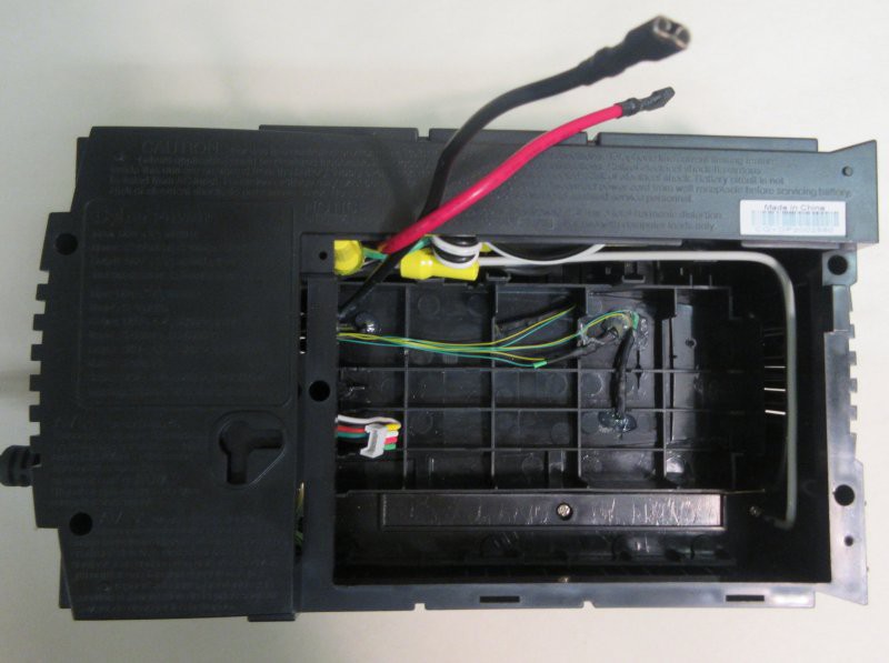
With the back on, it's just waiting to accept the battery. The programming header is visible, but it tucks out of the way.
The three outlet sets indicated by yellow LEDs are individually controllable, via commands coming in over RF. Here is outlet 2 off:
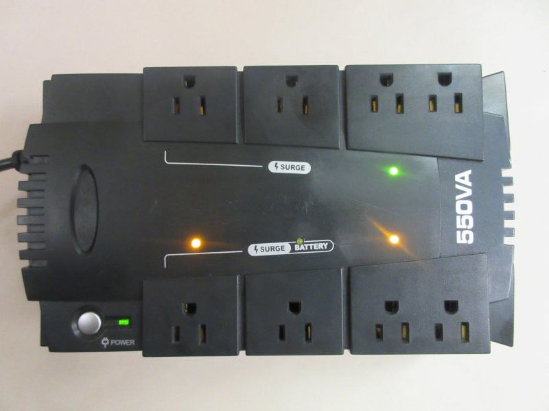
And outlets 2 and 3 off:
I guess that is not so exciting on its own, but that is OK with me. The exciting part is how it integrates, as simple as it is, with other simple nodes in a (desired) complexity-producing network. I do try to avoid undesired complexity. It is one of my governing paradigms.
Discussions
Become a Hackaday.io Member
Create an account to leave a comment. Already have an account? Log In.