 John Schuch
My entire project depends on the MAG-3110 sensor being able to detect and measure the field of the magnets buried inside my standard water meter. To test my presumption that it would I had to build a test system. It's really pretty simple. The brain of the tester is a PIC12LF1840 microcontroller. I'm using this because it's what I plan to use in the final design and software I develop for the tester can be recycled into the final unit. I chose the 12LF1840 8-pin PIC for a few reasons: First, it is a VERY low power part (expected to draw about 10uA with Vdd at 3.3V) and since this will be a solar charged battery powered circuit, low power consumption is crucial. Second, it has plenty of program memory (4K words). My background is electronics, not software, so having a little extra breathing room in the code space may be handy. And finally, this microcontroller contains a "MASTER SYNCHRONOUS SERIAL PORT" (MSSP). In short, the MSSP hugely simplifies programming the I2C bus, which is how the controller communicates with the MAG-3110 sensor.

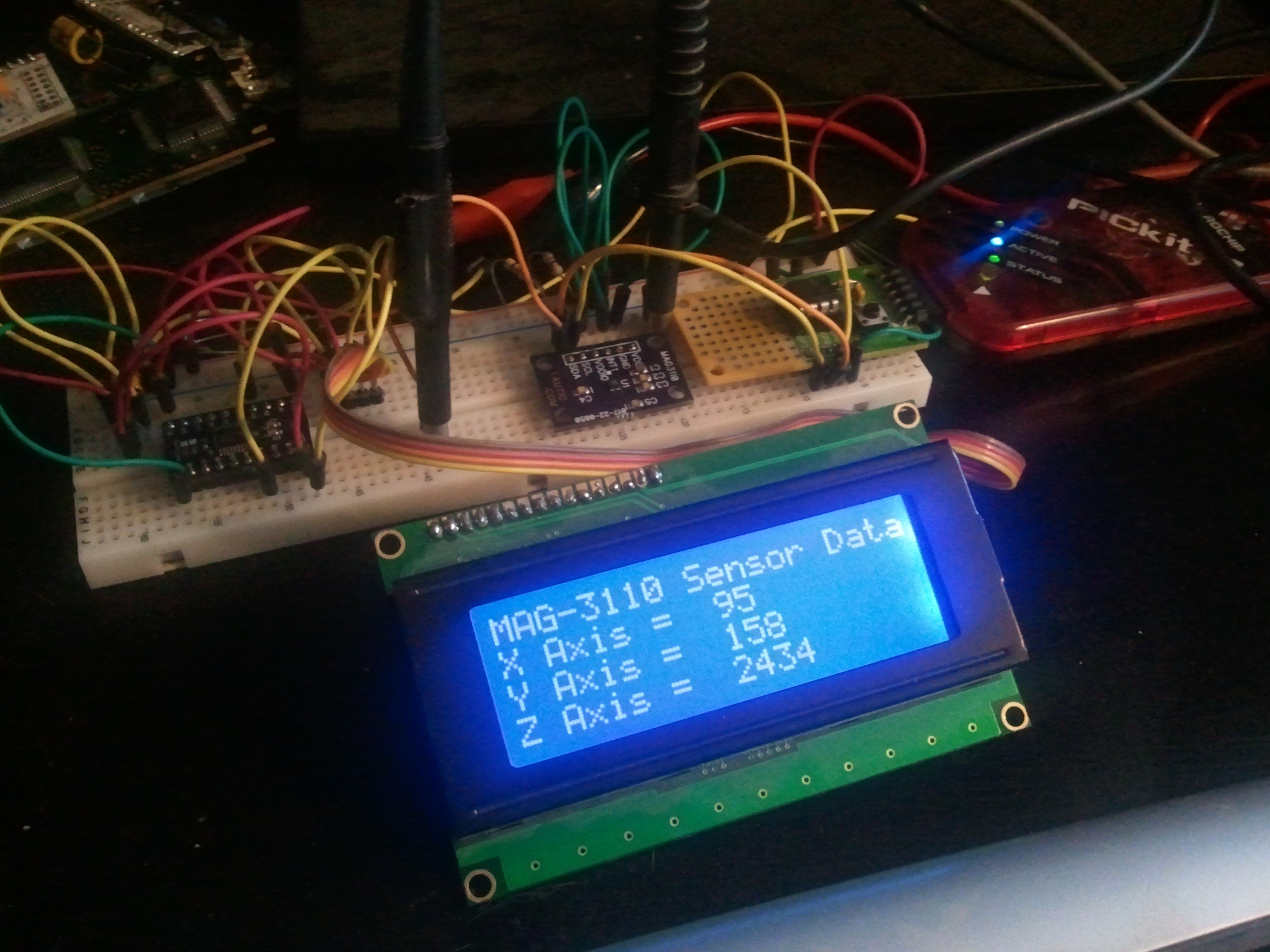
For this test I'm just going to me moving the sensor around the water meter, so obviously I need so way to see the readings in real-time. To accomplish this I added a 4 X 20 character LCD display. I also added a serial backpack to the display which allows the microcontroller to output data as RS-232 (as opposed to have to deal with all the pins required for a direct LCD interface). Again, this also allows for code reuse since the transmitter I've selected for the project accepts serial data. In the final design there will be no display at the transmitter end.
The microcontroller and sensor both operate at 3.3 Vdc, but the LCD display and backpack require 5Vdc. I chose to run this evaluation circuit off of batteries so I didn't have to drag an extension cord and a power supply out to the street for the test. The battery power is directed to a 5V regulator to provide power to the LCD and serial backpack. The 5V also feeds a 3.3V regulator which powers the rest of the circuit.
The final issue is that the microcontroller outputs a 3.3V RS232 signal, and the serial backpack requires a 5V signal. I dropped a level shifter chip in the signal path to boost the serial line to the proper voltage for the backpack. And as you can see from the photo below, it all works.
The source code for this evaluation circuit can be found HERE.
The next thing I need to do is build an extension cable for the sensor to get it off of the breadboard and allow me to position, and move it around the water meter. Since this is a one-time-use evaluation circuit I am just going to leave it on the breadboard. Once the test is done I'll be removing the display and backback, and replacing it with the RF transmitter (as well as rewriting the software for the microcontroller).
Discussions
Become a Hackaday.io Member
Create an account to leave a comment. Already have an account? Log In.