 John Schuch
So, I got a little distracted. I was thinking about the user interface for the receiver end of this project. I've always planned on using a 4-line LCD ( or VFD ) display to present water consumption data to the end user. But it occurred to me that once a person is used to the box sitting there they won't notice it much. Since the whole point of the project is to remind and notify users of their water consumption, I'd need to add something a bit more obvious as an output device in addition to the text display.
I decided that what I needed was a ring of LEDs. One LED would always be lit, and it would step around the circle at a rate that corresponds to the water flow rate as measured from the meter. When the user walked through the room containing the display it would be difficult to not notice the moving display, particularly if it's spinning madly indicating a large flow of water.
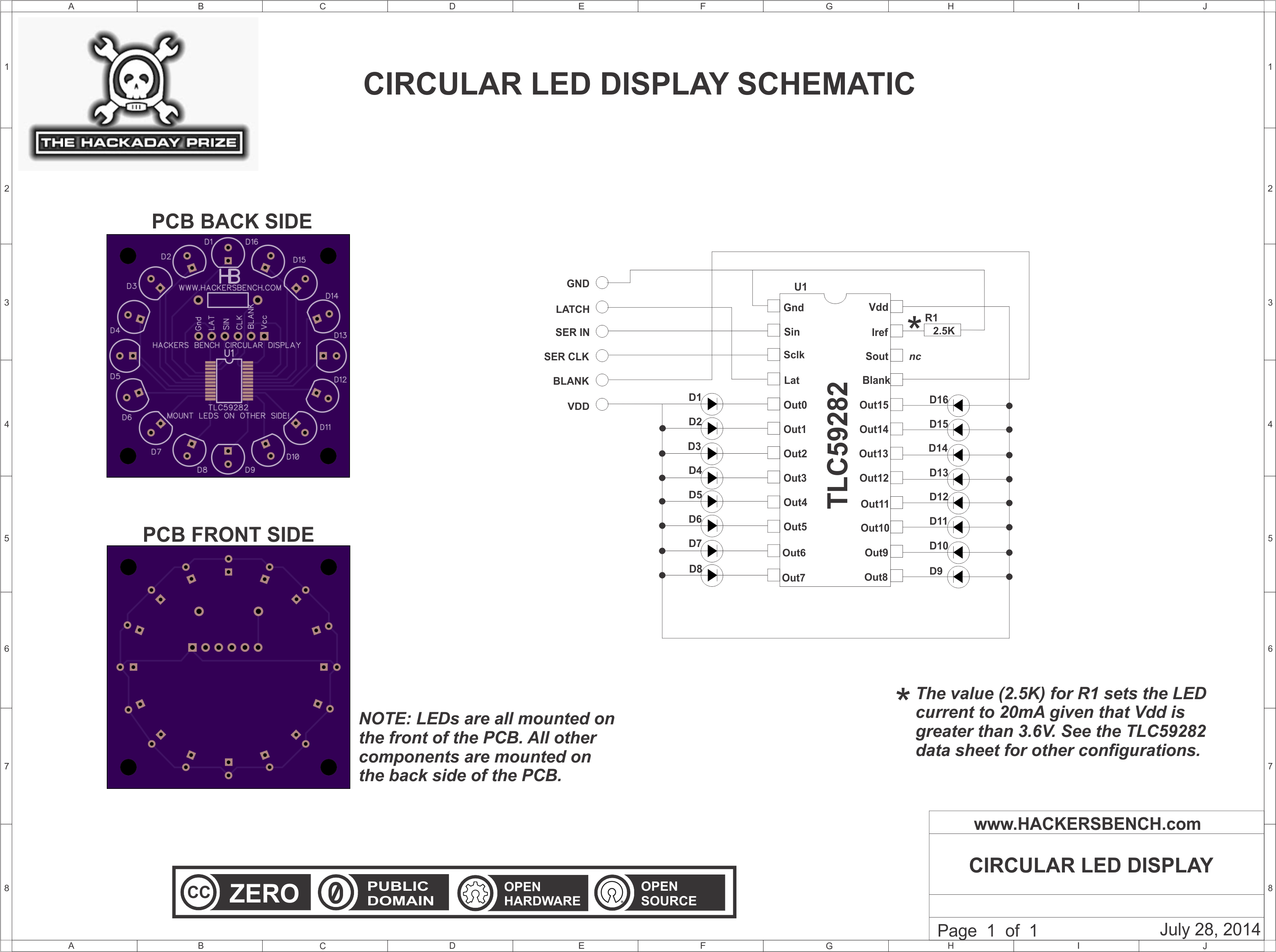
I felt that using 16 LEDs would present a nice, contiguous circle. If you look around the web you'll see dozens and dozens of people driving rows of LEDs with shift registers, like the 74HC/LS595. Unless they only ever turn on one or two LEDs at a time, they're all doing it wrong. The '595 can't handle that much current. To drive my display, I chose the TLC59282 from Texas Instruments, available from Digikey. This part is a 16-bit shift register, but it adds constant-current sink drivers to all the outputs. Choosing one resistor sets the current for all of the LEDs. Further, it has a "BLANK" input which enables/disables all of the LEDs.
It also occurred to me this circular display could be handy in other circuits and applications, so decided to make it a stand alone sub-assembly. I almost always breadboard my circuits before committing to a PCB design, but this chip is so simple that I went ahead and ordered PCBs and components at the same time.
NOTE: You can buy these boards! I will post links to the gerbers (when I figure out how) but in the mean time, if you would like to use this display board for one of your projects you can buy them (in sets of three) from OSHPark.com here. I do not make a penny off of this! I simply set up OSHPark to share my design, and others can order board sets directly from them.
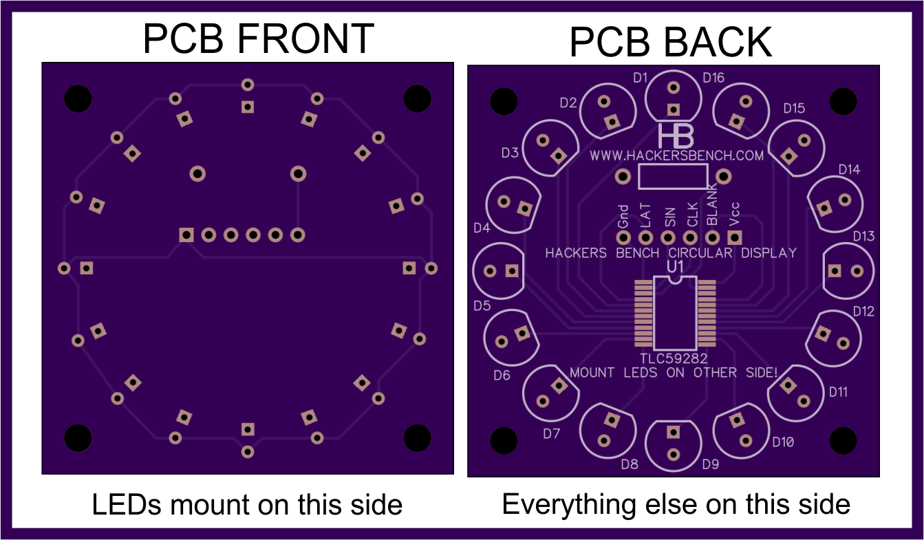
You COULD install all of the parts on the same side of the PCB, but my intent is to install the LEDs on the front side, and everything else on the back. If I end up installing this behind something like a tinted panel, I may want to paint the front side (before installing the LEDs) with flat black paint so that you won't see anything but the LEDs through the panel.
The single resistor sets the current level provided to all of the LEDs connected to the display. The data sheet provides a large table to select this resistor value based on desired current and supply voltage. In my case (5V supply, 20mA) the value came out to 2.5K ohms.
It took a little time to select the LED I used. I wanted it to be blue ( because ... well ... water), I wanted it to be in a diffused package so it wasn't glaring, and I wanted to to be fairly low power. I finally found the MT5470-BL, available from Digikey. I am very pleased with these LEDs except that they are still VERY bright, far too bright for this application. Luckily there is the "BLANK" pin on the driver chip. I set up the microcontroller (PIC16F1509 in this case) to generate a PWM signal, and applied that to the "BLANK" pin of the display driver. This approach worked very well, and I found that providing a duty cycle of about 5% on time gave me the brightness I wanted. What's more, if I have time this opens up the possibility of including an ambient light sensor and have the system automatically set the LED brightness based on how light it is in the room.
Now, in this application, there will be a single LED lit and it will progress around the circle indicating water flow. But, having the working board sitting here I could help but play with some other possibilities. Here's a video of a little demonstration program I wrote to show gratuitous flashing of LEDs. :-)
And finally, here is the schematic of the LED Circular Display.
This LINK will take you to a better printable version of the drawing.
UPDATE:
I've written a fuller description of this display board on my main website. You can view it HERE.
Discussions
Become a Hackaday.io Member
Create an account to leave a comment. Already have an account? Log In.
A wind up/wind down effect on this water wheel would be pretty cool. If you're washing your car or taking a shower you might not notice the display until you come back inside or have dried off, and if it's spinning at a low rate then the conveyance of that information may be lost.
Are you sure? yes | no