 Yann Guidon / YGDES
If you have followed the #SPDT16: 16-bits arithmetic unit with relays project, you will recognise a lot of elements. Actually, most of the important details have been solved :-)
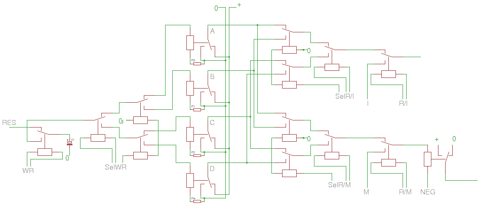
The first part of the datapath is incredibly obvious with SPDT relays, because they are natural multiplexers. Even the XOR uses a single relay:
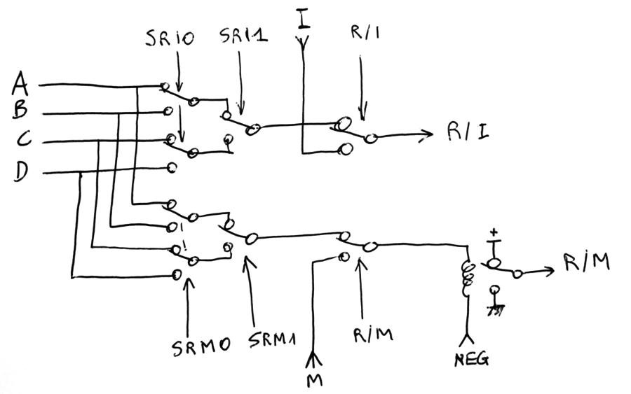
9 relays so far :-)
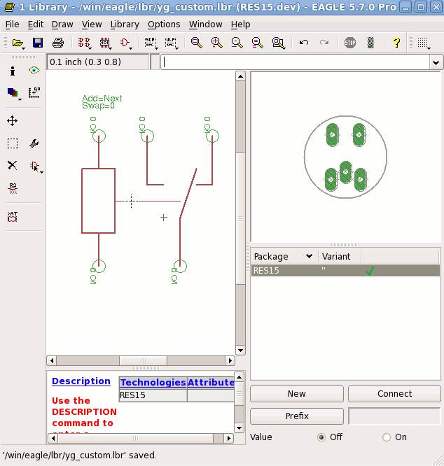
It's so simple that I had to make a component for Eagle:
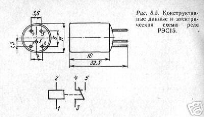
I have reused the little data I got from the seller:
 Now I can proceed with the rest.
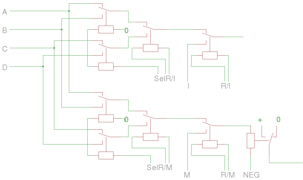
Adding the write logic and the latches is pretty easy.
Parts count : 17 relays "only" :-) Asymptotically, the parts cost is around 4 relays/bit (1 latch, two mux, one demux) (+4-3). I use the "hysteresis" approach for the latch, where a resistor is chosen to provide just enough current to keep the latch either ON or OFF.
I can already see that the control signals will drive A LOT of relays simultaneously. Considering the rather low current handling capability of the RES15, I believe that it is necessary to use higher voltages when the fanout is high. The relay's contacts will be stressed so current limiting resistors, capacitors and overshoot protection diodes must be designed.
I think that running the high fanout signals at 12V is reasonable, this could control about 6 or 7 coils in series. A 24V PSU is also possible for more fanout. Then, DC/DC will step this down to about 5V for the "logic" signals.
From the seller's description:
> Coil : 2.8V 60mA
> Switching voltage up to 150V 100mA
The coil's characteristics have been studied before (and are more reasonable) but this means that at most 2 relays can be driven in parallel... The backplane will have to take this into account, when it connects the coils in parallel and series. A multi-level amplification tree must also be used.
Furthermore, to reduce switching times, the coil's energy must be released/dissipated quickly. Different working voltages would make the coil's energy swing around the hysteresis point...
This will be a fancy and noisy heater for this winter.
The rest ot the datapath is pretty simple and is centered aroud a full-adder circuit as described at Rationale and general idea. It takes only 3 SPDT to compute one bit, as explained at Basic Relay Computer where you can find the following drawing:
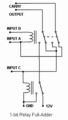
More relay tricks have been found at http://relaysbc.sourceforge.net/circuits.html
The above circuit computes the XOR between A and B but the output is also influenced by input C. Thus the normal output can't be directly used as a XOR, unless C can be disabled and kept low.
Merging the XOR and ADD signals saves one MUX input and one relay, though disabling the carry chain also consumes one relay... One stone, two birds : I add a "Carry enable" that is also a buffer that regenerates the Carry signal. This is necessary because the "input C" will progressively get more and more current, from all the inverting relays it will find along the carry chain...
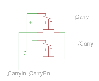
CarryEn will get a large load but will only switch to 0V, it might be handled by the control/backplane with a fanout tree.
Logc is easy as well and uses 3 relays:
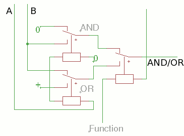
Overall the single-bit datapath uses 27 SPDT relays :-)
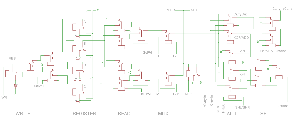
Somehow I managed to reduce the result's MUX8 down to a MUX4, though many sub-functions have been moved/transformed upstream. I'm quite proud of this achievement :-)
Note : I could have replaced the OR with diodes but... no. Because there are design rules that force me to be careful about driving strength and current direction. I would have had to add an amplifying relay in the critical datapath.
27 relays on the bitslice module, plus a few amplifiers on the backplane, let's say 30 relays/bit.
- 8 bits wide : 240 relays
- 10 bits wide : 300 relays
- 12 bits wide : 360 relays
- 16 bits wide : 480 relays
This is very tempting :-)
8 bits or 10 bits is reasonable, 12 bits will make a nice quad-octal (or tri-hexadecimal) machine :-D
However at 16 bits, the carry chain will use most of the cycle time. 16 bits is within my reach but might be an extra challenge...
So let's just try it as it is, evaluate the issues (delays, consumption, fanout, etc.) and see if the above design really needs any enhancement :-)
Discussions
Become a Hackaday.io Member
Create an account to leave a comment. Already have an account? Log In.