 Yann Guidon / YGDES
I have decided to increase the number of registers to 8.
This is justified by a few choices and enhancements. The first being that I'll map two memory spaces to the new registers, so they are not really registers. OK, they are, now, but they will be rewired, and the necessary MUX would have been put somewhere else otherwise so this is not really a significant increase in complexity or relay count. Actually, it removes the MUX that selects the operands (either the register or the external data, which is either an immediate from the instruction word, or memory).
The trick is that the constants will be injected at the ALU level with the ROP2 logic unit :-) so 2 MUX are "saved".
The relay count is increased to 32, including the result latch. This last part is pretty critical because the bounces lasts at least 2ms so the capacitor trick doesn't work. A 3-phases system is necessary:
- acquire/latch the result data (at least 2ms to stabilise the latch bit)
In fact this also corresponds to the ALU delay, as well as the time to switch the result MUX8. - turn the latch signal off (at least 2ms more). The result MUX8 must be stable by now.
- send the WriteBack signal, at least 5ms (2ms for the WB relay to switch then 2ms for the register latch to switch too)
In case writeback is not required (for comparisons, maybe ?) then some of these cycles can be saved and the instruction can run faster. If the result register is different from both operand registers, the latch can be short-ciruited as well !
32×16=512 relays... things get serious, and power consumption too ! A lot of power is used by the MUX8s and their consumption must be reduced as much as possible. See the previous logs about that. About 24 control signals must be driven....
I'll try to build a prototype of the following circuit, which is one bitslice:

It's going to be a pretty cute 8×4 array of cylinders :-D
The 8 latch relays will be on the outer edge of the board, to expose their value with a LED. The Glühbirnchen would be much better (visually) but they consume 50mA and already eat most of the switching capacity of the relays (100mA) and I still am not sure about the fanout in the ALU. In the beginning I'll use normal LEDs (green ?) and later, a set of 8 #DYPLED :-)
I couldn't wait and I started soldering stuff. Good news : 8 relays fit into 100mm :-)
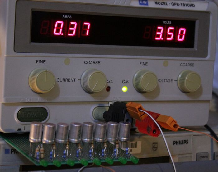
Power for 8 latches is 0.37A×3.5V=1.3W. Yes, more than 1W per byte :-D
And this is when the latches are cleared because the LEDs draw some current too:
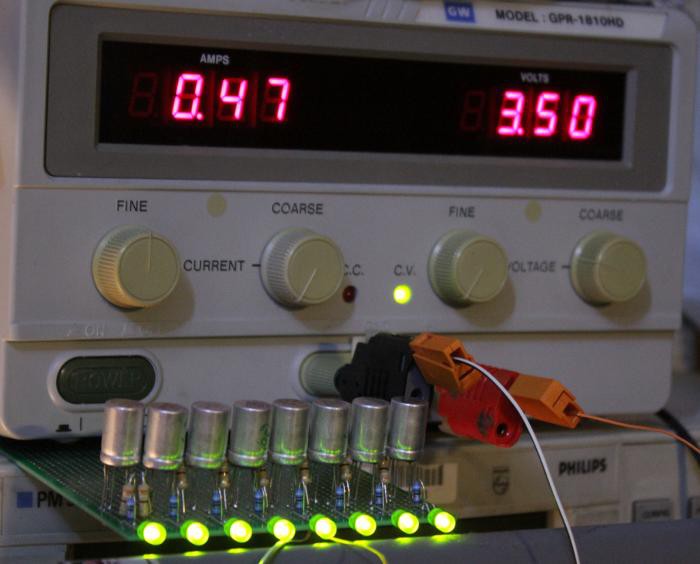
Yup, that's 1.6W :-D A whole set (16×8) will draw 27W.
No wonder this technology is not used anymore.
The first LED turns on at 3.6V and the first LED turns off at 2.55V.
Discussions
Become a Hackaday.io Member
Create an account to leave a comment. Already have an account? Log In.