 Yann Guidon / YGDES
The question of the relay quality has resurfaced and I want to characterize my stock.
What is their endurance ? The only way to try is to make them work, fast and hard, and see how long they last. The best circuit for this is a ring oscillator.
I have had bad experiences already (see the #SPDT16: 16-bits arithmetic unit with relays logs) but this time I know these relays better and I shouldn't make some blunders. In particular, the PBRL reduces wear on the contacts so a string of relays will do a good delay line.
Another interesting side is that the relays' speed can be measured, simply by the ferquency of a ring, depending on the number of relays.
The ring did not work as easily as expected, I had tried one or two relays in series but not 4 or 5.
Something I learned : decoupling is even more critical ! 470µF for 4 relays seems to work... Otherwise, I start to increase the PSU's voltage. With enough capacity, the voltage doesn't need to increase. They don't tell you that in the books !!!
OK, with the decoupling solved, the voltage becomes important. It drifts in a few minutes, and this can actually be seen on the 'scope, as the duty cycle is affected. The sweet spot seems to be around 3.8V..4V but it might change. It's important to find a voltage that works in cold and warm conditions.
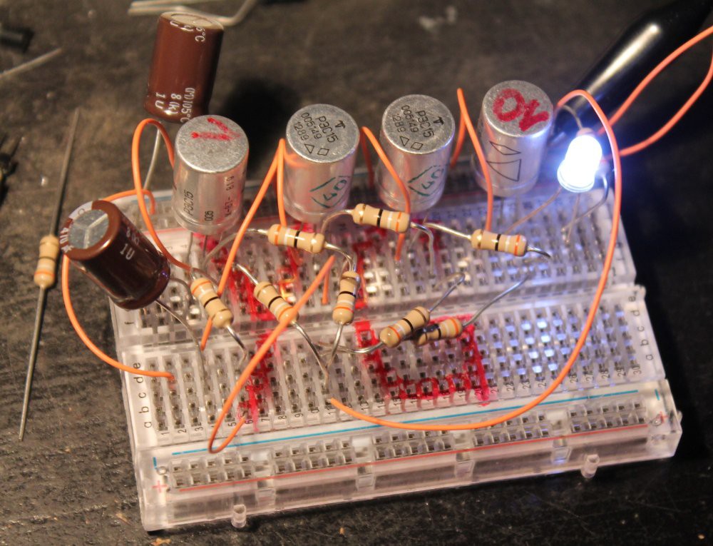
Because of the crazy quantity of bouncing, it's hard to measure a precise frequency. But I estimated the following:
- 2 relays: Tcycle=15..17ms
- 3 relays: Tcycle=23ms
- 4 relays: Tcycle=30ms
It seems that each relay adds about 7ms to the cycle time, which includes the high and low states. A relay seems to increase the chain's delay by 7/2=3.5ms, which is consistent with my previous measurements.
From this, I can estimate the cycle time of the circuits. If I can keep the critical datapath short (less than 7 relays), I could reach maybe 40 to 50 instructions per second :-D
I have left the oscillator circuit working for the night at about 43Hz under 3.8V (@0.21A), and I will see tomorrow how it has aged... That's about 150K cycles per hour, or a million cycles in 7 hours. I know it's not signifiant because I should test more than 4 relays at once (20 ?) but it's a start.
And yes, those prototyping breadboards are not reliable... But my first try with a soldered board didn't work, I suppose by lack of decoupling.
Bad contacts stalled the circuit 2× in 1h already... I must solder that circuit.
3h later: the circuit stopped several times already. I must change the voltage to 3.4V because the working range was reduced to 3.21..3.75V (below the 3.8V I had initially set). When I started, it worked up to 4.1V...
For the next systems, should I "burn-in" the relays for a few hours ?
Almost 12h later: the working voltage range is now about 3.3..3.8V. I've set it to 3.5V. Just like I computed in the first PBRL log. I don't know if the ambiant temperature has affected it...
If I'm ever doing a computer with this, I'll have to add a diagnostic and tuning mode to set the POL DC/DC.
18h later: the range has been reduced to 3.25..3.65V so I set to 3.4V.
I should probably increase the bias resistor and halve the series resistor. The control current will be doubled but the working range will be greatly extended.
25h later: still ringning. The voltage range is now 3.4..3.7V => set to 3.5V.
Ambient temperature : 15°C.
I can't make sense of the variations of the range. Is my lab PSU faulty ?
However the current remains stable: 0.20 to 0.21A.
Yes, relays should be considered as current-driven devices.
28h later: it stopped ringing. The relays work but the range (3.45..3.65V) has shrunk too much for a reliable system. I'll see how long it works at 3.55V.
I've never seen such an erratic-looking behaviour, the range variations are hard to explain or to model. I must design a better set of resistor values.
H+36: Still ringing. The range didn't change much this time, did I reach a plateau ?
H+42: still clicking. That should now make about 6 millions of on-off cycles.
Discussions
Become a Hackaday.io Member
Create an account to leave a comment. Already have an account? Log In.
It seems very finicky... Imagine a design with thousands of these relays that each needs to be hand-tuned as they age, and as the computer warms up....
Is it possible to "detube" the resistors so you get a bit worse performance but a better working range?
Are you sure? yes | no
To be fair, I'm not really worried. The most finicky place will be the register set because it uses the relays in hysteresis zone. A special, adapted wiring will isolate the power supply from the rest of the circuit to prevent interferences. I have seen that decoupling is not to be taken lightly so that's why I scrap the first "bitslice" and must build a new, better one.
Actually, the "PBRL" parts are quite few in the AMBAP design, which is mostly made out of centrally-controlled high-fanout relays. Pre-biasing will occur in few places and not all in series, whereas the relay ring oscillator uses 3 PBRL buffers in series: the working range is a combination of all the individual characteristics.
The high-fanout parts will drive the relays in a more energy-conscious way, pre-biasing to only 10mA and driving to maybe 55 or 60mA. These are current-drivent devices after all...
This computer architecture is "mostly" made out of centrally-controlled multiplexers. There is quite few arbitrary logic. And now I know to be even more careful. I even wonder how to run auto-tests...
Are you sure? yes | no
Nice! This is a great way to characterize the relays for logic service. I'm sorry that I only learned of this technique recently (from one of @agp.cooper's logs). I could have used it a few years ago for characterizing diode logic.
I didn't notice any diodes on your breadboard. Are there diodes inside the relay cans? (my batch hasn't arrived yet). Without diodes to absorb the energy from the coil decaying, won't you arc the contacts of the previous stage and reduce their lifetime? Of course, it slows the release time, but you can work around that with an additional zener shown here:
http://jumperone.com/2011/10/using-relays/
Aesthetically, though, maybe you don't want any diodes - that of course, is your decision :-)
I sketched some notes the other day about possibly using some "steering diodes" to re-cycle the energy when a coil is de-energized. Depending on the circuit, there may even be enough to pull in the next stage relay (still thinking about ring counters).
EDIT: are your 39R resistors absorbing the kick?
Are you sure? yes | no
a) which log ? I might have missed the memo...
3) the "kick" is simply not generated. Look again at Maxwell's equations ;-) I drive the coil will the smallest possible voltage delta so the current does not vary enough. And yes the 39 Ohms resistor does the rest. But it's already explained in a precedent log:
https://hackaday.io/project/14628-ambap-a-modest-bitslice-architecture-proposal/log/45484-my-first-pre-biased-relay-logic-gates
I'm not sure your steering scheme will work, relays are much more complex than we like to think...
Are you sure? yes | no
a) https://hackaday.io/project/12885-a-discrete-transistor-7400-nand-gate/log/42860-testing-propagation-delay
Interesting; I'll have a look at the other log.
Are you sure? yes | no
I hadn't taken a close look at the biasing scheme before; the excess magnetizing current gets dissipated in the biasing resistor when the relay drops out. Nice.
Are you sure? yes | no
Not only that but the biasing reduces the current swing, hence the reduces the kick energy.
In practice, there is not even a need for a capacitor across the coil pins.
Are you sure? yes | no