 Yann Guidon / YGDES
Oh my, another acronym... CCPBRL doesn't particularly roll on your tongue :-D
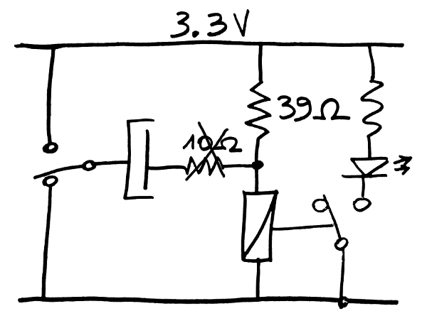
The preliminary design of the RAM made me wonder about the values and characteristics of the parts: the storage cap, the sense relay, etc.
So I experimented and the result is pretty awesome.
Against my initial intuition, this system works well.
First, as a purely logic system, the capacitive coupling actually reduces the average operating current. It also helps to extend the operating voltage range a bit. The series resistor might be useful, but not necessary. This new system swapped a passive part for another, which enhances the circuit ! I'll have to see if this also increases the speed.
I'm working with 100µF but it is functional with 22µF & 10 Ohms. The lower limit might be around 10µF but I couldn't find one in my parts bin... 6µF is not enough though.
As a RAM storage component, the retension/refresh period could be in the minutes range. The series resistor would be removed. Oh and it works with a single voltage, no need of complex diodes or higher voltages ! However, the 1N4148 silicon diodes drops 0.7V, I have to check if this still works...
Now it's funny how, by looking at the RAM part, I discover how to enhance this already simple and efficient circuit !
Time to find the cheapest capacitor bulk suppliers...
Discussions
Become a Hackaday.io Member
Create an account to leave a comment. Already have an account? Log In.
Nice. So the relay is *just about* powered-enough to pull-in, via the 39ohm resistor but *not quite*... then giving a tiny surge of positive voltage, the relay pulls-in, and the 39ohm resistor gives just enough current to maintain the pulled-in state...? Then, switching to the ground-position, the opposite happens, the relay releases and stays...? Clever.
Is there any benefit to having a center-off switch driving this system?
Are you sure? yes | no
Well, you described the effect of magnetic hysteresis, which I use in many places :-)
And with 100µF, the surge is not "tiny", I should measure the current (through 1 Ohm in series ?) but the relay needs about 20mA for enough time to actually move.
I have no "center-off switch", I used a SPDT to choose the voltage, and a push-button, to simulate the circuit.
Are you sure? yes | no
Ah, so you do actually have an "off" state, where one side of the capacitor is floating or not connected to either rail. Wasn't sure whether this circuit relied on the capacitor always holding a charge... with a full-off state, the capacitor would eventually leak to 0V, right?
In another log you mention using a two-output voltage-source for another purpose... couldn't you save the bias-resistor by using a smaller "hold" voltage, or is that too sensitive to other goings-on with the power-rail, etc.?
Are you sure? yes | no
Here I'm just examining one "test" circuit. The expected, more complete circuit is shown on another log (both electrodes of the capacitor are disconnected to make a 2D array). But there are some fundamental differences that I'm still trying to grasp...
about your 2nd paragraph : please include a schematic so I "get" what you wrote :-)
Are you sure? yes | no
Nah, I realize now that idea's ridiculous. It could *maybe* be accomplished with two supply-voltages and a diode rather than the resistor, but even that would be ridiculous ;)
I missed the fact that the resistor (39ohm) helps to isolate the power-source going into that resistor from the switching-voltage.
Are you sure? yes | no
ridi-what ?
:-P
Are you sure? yes | no