 Yann Guidon / YGDES
In the previous log Capacitively Coupled Pre-Biased Relay Logic I have characterized a new twist on the prebiased relay circuit. But the RAM cell contains more than a capacitor, there is a couple of diodes. It was time to verify their influence on the circuit.
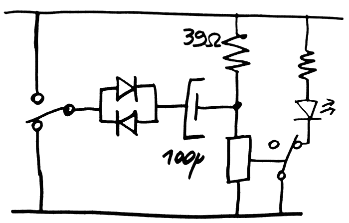
The bad news : the working voltage range has shrunk to only 3.35-3.75V, giving an ideal voltage of 3.55V. That's a very narrow tolerance (+/-5%) and kills my hopes of using a dumb unregulated tranformer, as any ripple will be an outright parasite. The range also varies with the frequency of the signal, as the capacitor is charging through the 39 Ohms of the coil and the resistor. This explains why the working range is pretty symmetric this time.
For this circuit, I'm using the eternally famous 1N4148. You can get them in bulk quantities for "dust" price, only resistors can be cheaper... The drop voltage is around 0.7V, less at small currents, but in this case it only deals with spikes. The instant drop might rise to 1V or more, with no limiting resistor.
How can the range be extended again, providing more ripple noise immunity ?
- First idea is to use Germanium diodes. I love this idea because it "feels true" to the spirit of the retrocomputing. The drop voltage is halved and that gives about 0.7V of additional range back. However sourcing 1000s of them will be much less cost-effective than the 1N4148 (whose prices can go lower than 0.005USD/pc) and they are rated for a lower current (usually 20mA for point-contact Ge diodes such as 1N60). I don't want to push this limit.
- Then the logical contender is to use Schottky diodes. Cheaper, bulk modern stocks, available in all sorts of ratings. I have a reel or two waiting to be used but it's too modern and does not have the "dirt cheap" appeal of the 1N4148 in axial packaging. I'd like to keep through-hole parts for easier manual soldering, SMD is great but not in all the cases.
- Figure out a charge pump trick to over-charge the cap ?
Wait. In the above circuit, the cap is only charged mid-way (Vcc/2) through the resistors, and a write circuit must reinject a full-swing voltage, not Vcc/2.
Approach 3. now makes sense because it's not only "dirt cheap" (the 1N4148 are not a major expense in the project) but also faster. The cap is charging through resistors and the 100µF takes a while to reach a voltage that allows the next cycle to trigger correctly. I have tested the thing manually at a few Hz but I'll need a faster (50Hz ?) system !
Yes, now it becomes obvious that the cap is charging in average to Vcc/2=1.6V, after it has delivered its "kick". There is the need to recharge it, if the bit was found to be "1". To write a "0", just inhibit the rewrite, or do like the below circuit (to be tested). The "cost" is "only" a second relay per bit of datapath. There were 16 relays, now 32, that's one box of RES15 :-D

To increase efficiency, I've imagined a diode which prevents the cap's current from flowing back to the supply rails. The diode adds some drop, which is compensated by the adjustable resistor in parallel with the main bias resistor. This could allow fine-tuning of the sensitivity.
I'm getting nervous about the sequencing of the control pulses of the RAM now...
There is the W/R pulse to generate at the proper time. I hope that this version works well because other versions need the sense relay to be "cleared" before "read", which adds more relays (to de-energize the sense coil) and more sequencing to do.
Oh and I forgot a critical aspect : how do I write data ? That's one more MUX/relay...
Furthermore, if 100µF is not a concern, the whole word will use 16 bits. Writing a word means charging 1600µF, more than the typical 470µF decoupling capacitors. A small series resistor is required on the write line...
And now here comes the actual trick question!
Why does this RAM array even uses diodes at all ?
Using relays, it's possible to connect both electrodes of the capacitor to form a 2D, and even 3D assembly. The more I look at it, the more I fail to understand what the diodes bring. It may have been useful for TIM-8 but here ?
....
Gone are the diodes.
Discussions
Become a Hackaday.io Member
Create an account to leave a comment. Already have an account? Log In.
There's Schottky's, too. Less "authentic" but also less costly than Ge diodes. Then again, if you have a bunch of Ge transistors, you can use them as diodes - oh, nevermind, what am I saying...transistors, ha!
So, I was thinking about your voltage issues. Do things really change as the relays warm up? I looked up the resistivity tempco of copper (assuming copper windings). It's 0.00386. So dR/R = 0.00386 dT. For a 13-degree C rise, you're outside the 5% tolerance - if I did the math right. I wonder if you can find a 39-ohm NTC thermistor to cancel out the coil tempco.
Oh, this is actually a thing:
http://www.ametherm.com/thermistor/ntc-thermistors-temperature-compensation-circuits
Are you sure? yes | no
Re: Ge and Schottky : let me finish writing :-D
I'm forced to update often because my browser keeps crashing, taking with it my rants to bits paradise...
Re: Ge Transistors : you found out why I bought my first few russian dirt-gatherers :-P However in this project I would need both NPN and PNP because the diodes inside a transistors are not in the right direction. Ge NPN is rare and expensive. I got silicon PNP but it's not as cost effective (1N4148 still beats it easily).
Re: NTC: I'm trying to find a reliable circuit that works well without compensation. It keeps the design cleaner, more reliable, cheaper, easier to use, understand and expand...
Are you sure? yes | no