 Yann Guidon / YGDES
Edit 20170402: This entry is now moot/obsolete because of the approach explained in More balanced trees !
However this log is a very very interesting discussion that can be useful for other similar cases.
The last log How to balance a fanout tree has shown that it is possible to organise the coils in such a way that they are wired in strings on each (identical) bitslice board.
This greatly reduces the complexity of the boards and the number of signals on the backplane connector. OTOH this shuffles the bits all over the place and the backplane must reorder everything.
I have decided to implement parity checks over the DRAM read/write, as well as the register read/writes. There are 16+1=17 identical boards, parity is calculated on the 16 data boards and stored on the 17th board, using the bypass signals.
As a consequence, there are several "shuffled busses":
- 3 address bits for the write register
- 3 address bits for the read/I register
- 3 address bits for the read/R register
- 4 address bits for the memory line
- 5 address bits for the memory columns
(the columns are still not well defined, but must be considered and studied)
The "balanced shuffling" has been designed for 3 and 4 lines and 16 bits. However now it's 17 bits and the 5-bits shuffling is a new challenge...
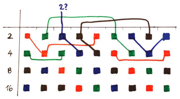
Let's start with the 3×16 balanced shuffle.
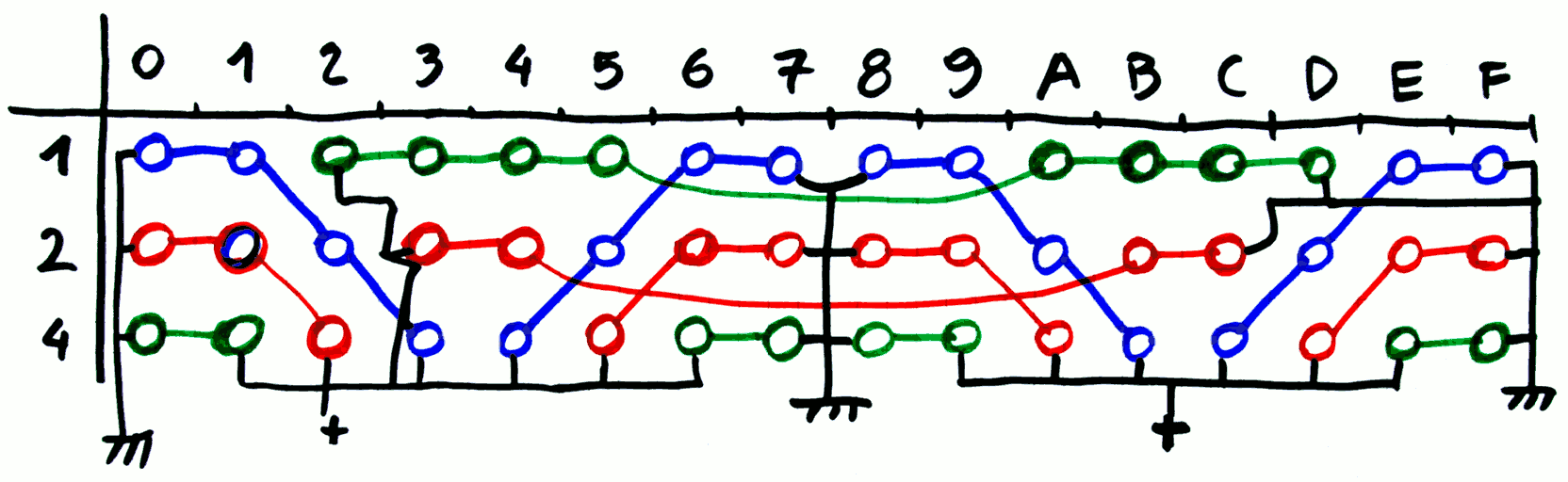 There are:
- 4 strings of blue
- 5 strings of green
- 5 strings of red
Then there are 3 strings of 1, 2 and 4 coils to add at the end.
But I have not yet studied the fanout of a CCPBRL gate to several 12V, 8-coils strings. So how many parallel strings can one relay drive ?
Another "EMI reduction measure" is to switch approximately one half of the coils to 12V, the other half to 24V, thus reducing the draw on the power rails and halving the decoupling capacitance.
20170320
The above routing works for 3 and 4 control lines with 16 bits, but more bits are needed and 5 control lines might become impossible to route.
17 is a prime number and does not look easy to use/partition. However the next number 18 is 2×3×3 and is great for use with "rotations" partitions. The would be one resistor per bit but that's a theoretical limit (I checked the numbers) and that's not a huge loss, the layout will be a bit less complicated.
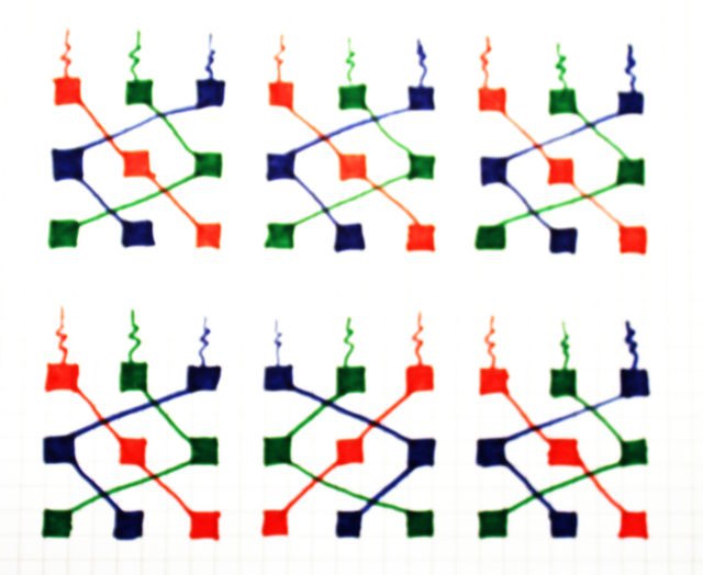
Here are two possible routings for one half (9 bits) of the slices:
However 4 and 5 are not easy to partition with 18 bits but there is a bit of hope. A recent log "CC-PBRL : Magnetic hysteresis and fanout" has shown that strings can be 4 or 6 coils long as well.
There is another interesting thing ! Past the 3 address bits, the other lines (with 8 and 16 fanins) "behave" differently because they are integer multiples of the required string length. The partition procedure can use more heuristics and various steps to reach the required balance. For example, we can start from the address line with the highest fanin then refine...
However the numbers start to look unfavorable.
- 4 address bits: 1+2+4+8=15 fanin per bitslice, 15×18=270 fanin total, or 67.5 fanin per bit, or 8.43 strings of 8 coils per address bit
- 5 address bits: 1+2+4+8+16=31 fanin per bitslice, 31×18=558 fanin total, or 111.6 fanin per bit, or 14 strings of 8 coils per address bit
The memory decoder is going to be a MAJOR fanout problem...
20170324
Let's apply some basic logic.
It is possible to get a number that is a multiple of 3, 4 and 5 by simply multiplying them all together.
3×4×5=60 : this is not a convenient number !
3×5 = 15 : that's too low, even though making a 14-bits computer is not impossible (though slightly unpractical)
17 is prime, forget it.
18 is nice but not a multiple of 5.
How is it possible to dump this dependency on this number 5 ?
The next number is 6, which aligns neatly with 2×3 and its multiples (18...)
This number 5 comes from the 32 relays, or the 16 pairs, that steer current at the columns of the DRAM arrays. The array is a 16×16 capacitors memory, creating a 256-words addressing space. Going from 32 to 64 relays increases the memory space to 512 words (or 1Ki bytes if 16 bits are used).
....
Driving 64×18=1152 relays must create insane inrush currents and that's probably the highest fanout of this project. That's 144 strings of 8 relays, 8 strings per bitslice. I must implement a local buffer : a relay (with fan-in of 1) will drive the 8 strings of 8 relays.
This FI1 signal is naturally in series with the FI1 signal of the root's MUX2, which simplifies a rotation-based partition.
OK the above is actually wrong.
Here are the actual "shuffled busses":
- 3 address bits for the write register : Fanin 1, 2, 4
- 3 address bits for the read/I register : Fanin 1, 2, 4
- 3 address bits for the read/R register : Fanin 1, 2, 4
- 4 address bits for the memory line : Fanin 1, 2, 4, 8
- 4 address bits for the memory columns : Fanin 1, 2, 4, 16
The mistakes I made in the initial problem statement are in bold face.
The missed detail is that the final level of the column drivers is doubled : two relays are necessary to switch both diode rails of each column.
These numbers are valid for a 16×16 words array (256 words, 512 bytes). That's pretty decent (with 4K capacitors). For 18 bitslices, that's 38×18=684 decoding relays... I have already settled for 256 words because a larger DRAM bitplane would be larger than 10×10cm. I am considering stacking two DRAM bitplanes but it is appearent that this extension should not be on the columns, but the rows because the last column's relays are doubled.
Estimates for a 512 words memory :
- 5 address bits for the memory line : Fanin 1, 2, 4, 8, 16
- 4 address bits for the memory columns : Fanin 1, 2, 4, 16
total : 54 relays per bitslice instead of 62.
For 18 bitslices, the cost is already 18×54=972 relays... or 1/3 of my current stock. There is still a 1/8 ratio of relay count vs bit count, which is a good sign.
OK my permutation problem is still unsolved.
Damnit !
I got the columns wrong again !
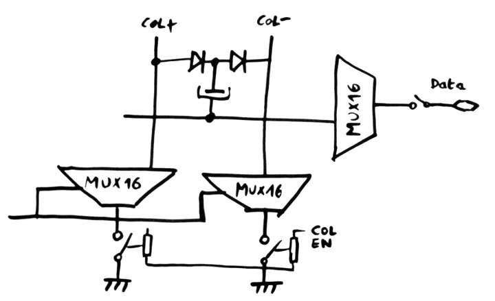
the MUX is actually a normal MUX16 BUT the end goes to 2 relays' middlepoint. So the actual Fanin is 1, 2, 4, 8, 16 just like the normal MUX16 but with one more layer.
D'oh
20170330
I got it all wrong again !
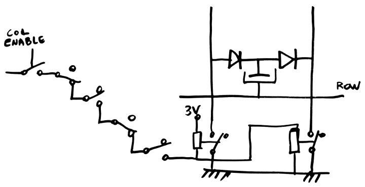
The column drivers are not optimal in the above configuration : driving 16 pairs of columns requires a 15-relays MUX16, then 2×16relays to switch the columns to 0V. That's a 3N factor, with a total of 47 relays ! Plus, the timing and power draw is not good.
If we accept to duplicate the tree of the MUX16, there are only 32 relays (or 2N) with the switch to ground at the root of each tree. The fan-in has doubled, though, but it might help a bit (for the permutations, see later) Power draw is better as well.
(Yes I've drawn the storage cap in reverse polarity)
For a 256-words memory :
- 4 address bits for the memory line : Fanin 1, 2, 4, 8
- 4 address bits for the memory columns : Fanin 2, 4, 8, 16
16+32=48 relays, and not 38... 864 (total for 18 planes), density : 5 bits/relay
For a 512-words memory :
- 5 address bits for the memory line : Fanin 1, 2, 4, 8, 16
- 4 address bits for the memory columns : Fanin 2, 4, 8, 16
That's about 64 relays, 1152 for 18 planes, 8 bits per relay : this is more favourable...
But the initial problem still persists !
Each board has MUXes of 3, 4 and 5 bits wide addresses .
However the double tree of the columns makes me think of a heuristic to partition the domain easily : for the case of 18 planes, work the partition with 9 planes, but instead of replicating the partition somewhere else, dupliate it with a shift/interleave. This turns the fanin1 look like fanin2, fanin2 becomes fanin4 and fanin4 becomes fanin8, which somehow "disappears" because there is no need to group it.
In the above drawing, each column represents a pair of bitplanes. The 9 columns get expanded into 18 bitplanes.
The resulting permutations are easier and the case of 4 addresses with 18/2=9 positions is pretty easy because only 2 lines (fanin 2 and 4) put some pressure. The only dissatisfying case is one blue string with only a length of 6, which is barely a problem, compared to other configurations, such as the previous 3:3, that require 1 resistor per bitplane...
The fanout per color is pretty neat : red=8×8=64, green=8×8=64, blue=(8×8)-2=62, black=10×8=80
But even the 3-lines case can benefit from pairing/doubling, the new version saves many resistors now. There are however pairs of relays (2 red, 2 green and 2 blue each) that need special care.
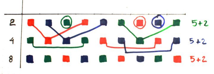
The fanout is totally balanced : 42 relays to drive from each address signal.
The case of the 5 addresses is more complicated (tm).
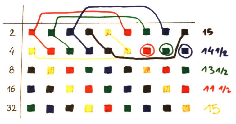
First, the 2x trick works but we get three dangling strings of 4. We would need a second MUX32 to merge the two halves. The fanout gets LARGE too ! 15×8=120 relays to drive the black or the yellow signal...
The deal-killer is that the 5-bits address is considered for an expansion of the memory, from 256 to 512 words. The process of going from 4 to 5 is really too convoluted. It would be easier to have two 4-bits fanout trees and a 5th address bit to select the proper MUX16, but this adds an "alternate address bus" to the layout...
Discussions
Become a Hackaday.io Member
Create an account to leave a comment. Already have an account? Log In.