At the beginning of 2014 I decided to make a 3D printer. I had been following along with the rapid developments (and falling costs) of making a RepRap inspired printer. I'd read many blogs and scoured forums for ideas and inspirations. I figured that accessible 3D printing was mature enough and now was the time for me to make my own. I did a fair amount of research and decided to challenge myself and design my own printer (rather than directly copy an established design). I intended to “stand on the shoulders of giants” and incorporate as many nice design features I saw as possible.
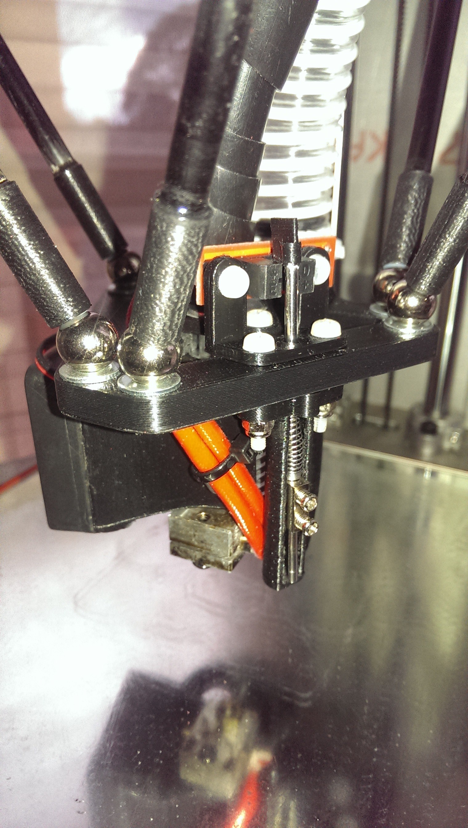
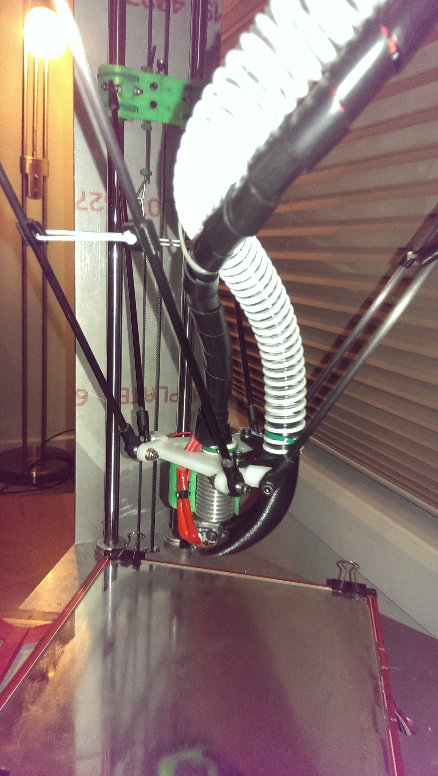
I stumbled on the Rostock design and was impressed with the delta mechanism and the high build-volume-versus-footprint ratio. I was also impressed by the symmetry and somewhat hypnotic movements while printing.
I came up with a few design goals that I have mostly achieved:
- Must be complete and printing well for under AUD$1000 (approximately US$950 in Q1 2014 of the project, about US$750 equivalent Q3 2016).
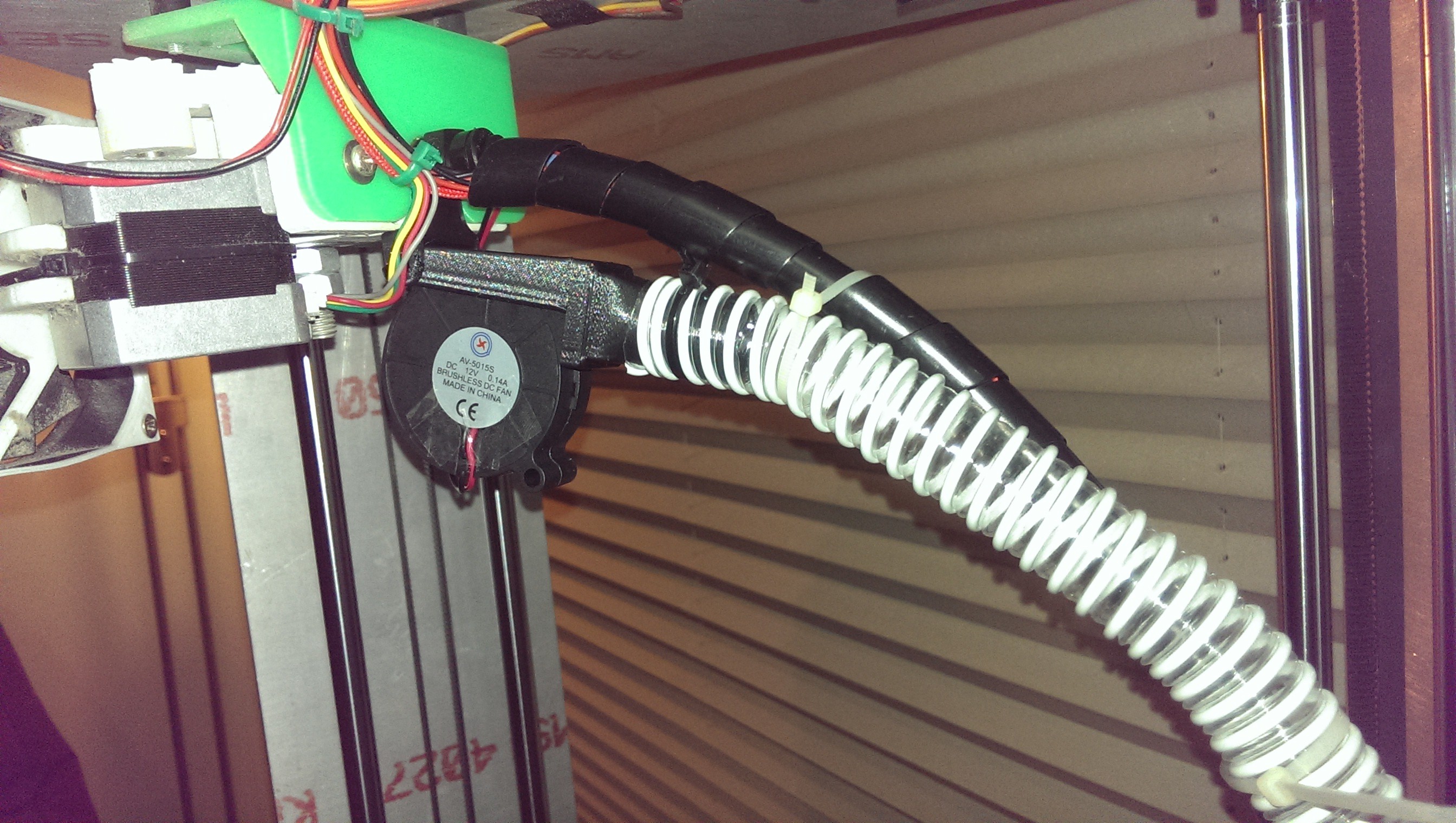
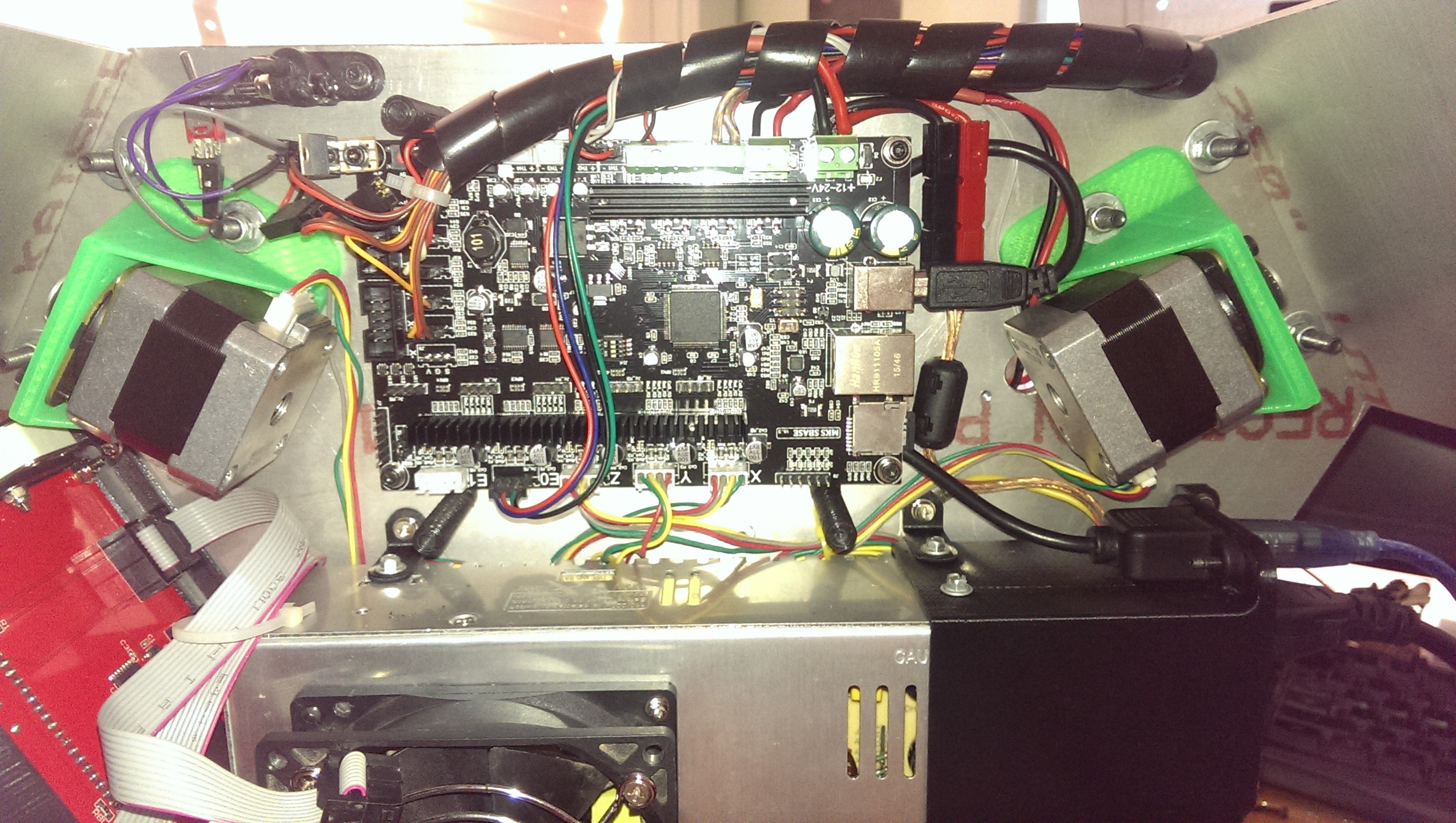
- All mechanics and wiring, including power supply, to remain within the triangular footprint of the printer.
- Integration of ideas from other 3D printers.
- Use as many off-the-shelf parts as possible. I am a big advocate for not reinventing the wheel. I ended up sourcing 90% of my parts from online stores such as eBay, HobbyKing and AliExpress.
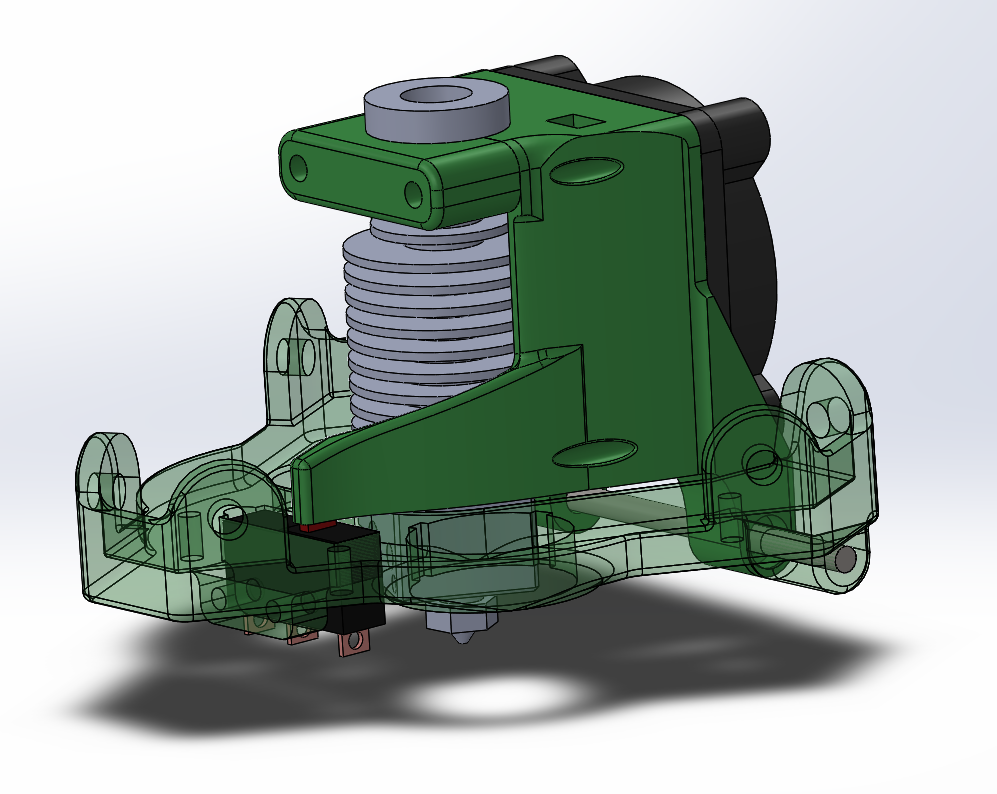
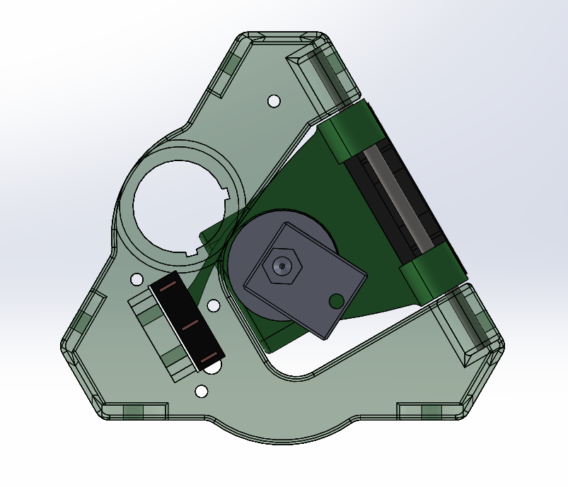
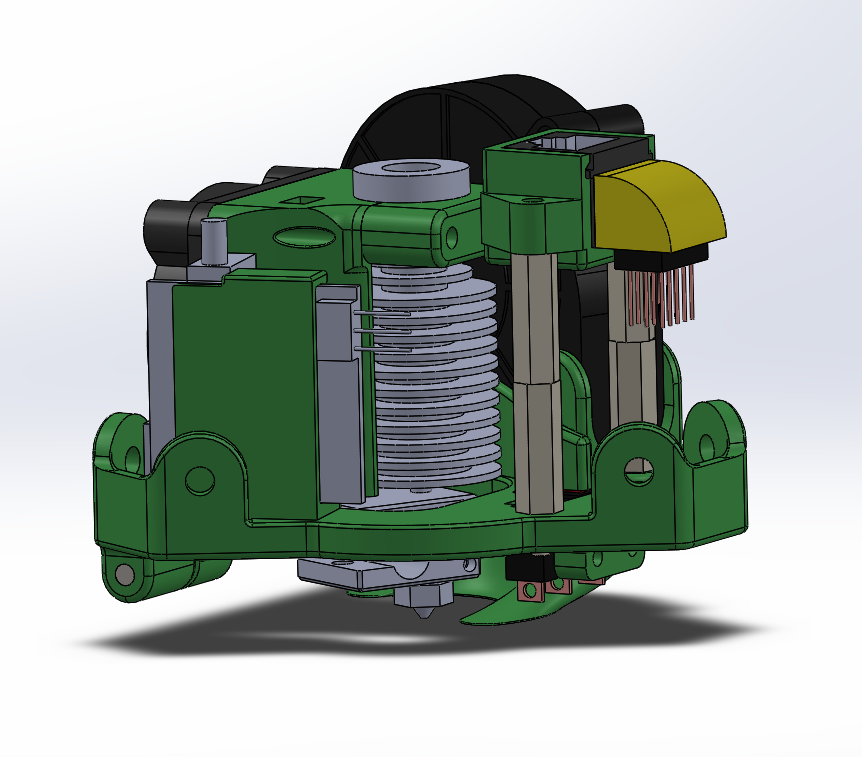
- Design as much as possible using CAD software to ensure that all components would fit together. This also had the added benefit of identifying many design issues or fundamental flaws early on – before any money has been spent.
- Manufacture at home with simple hand tools and a drill. I don’t have a shed or workshop so most construction activities occur in my apartment, with occasional visits to friends and relatives’ sheds.
- Be able to practically dismantle the entire printer if required. This means nothing permanently glued, nuts and bolts instead of screws, no complex assemblies and “design-for-servicing”.
- To replace non-printed hand-manufactured parts with printed refined designs where practical.
I have enjoyed this project immensely and, as it nears “practical completion” I thought that I should share it with the world. Hopefully it can provide ideas and inspiration for your own 3D printer.
Current Specifications:
|
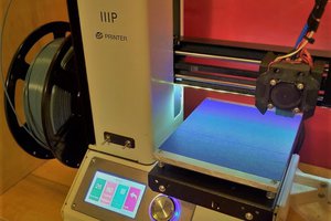
Print Area/Volume |
270mm diameter cylinder, 350mm high (10.6in x 13.8in) |
|
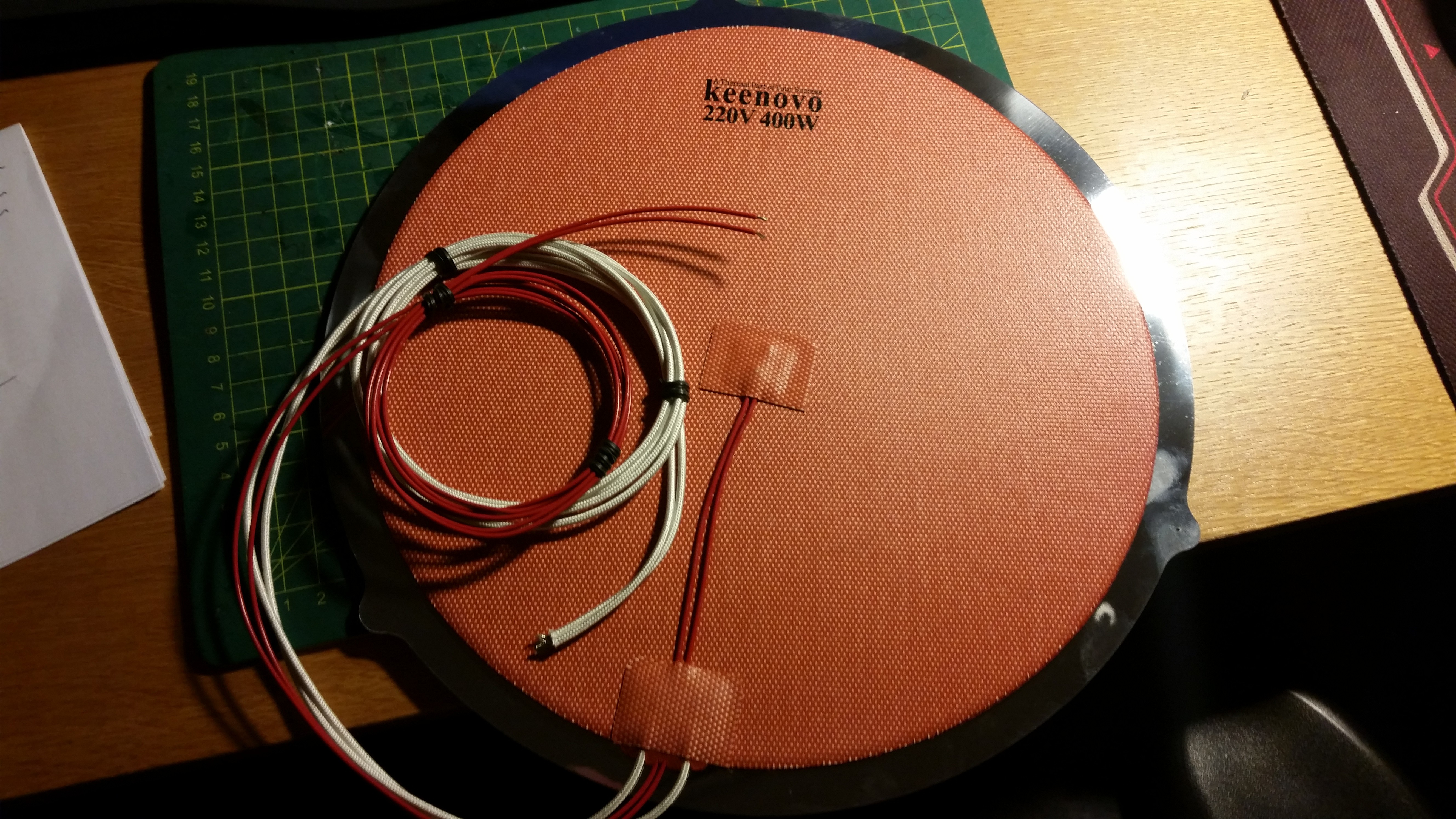
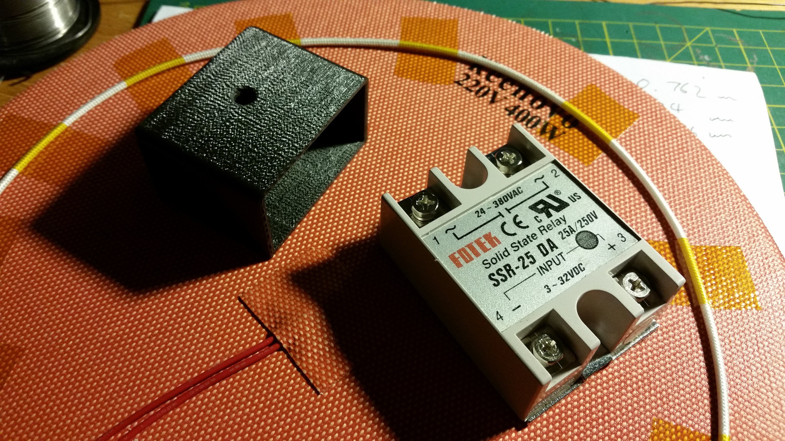
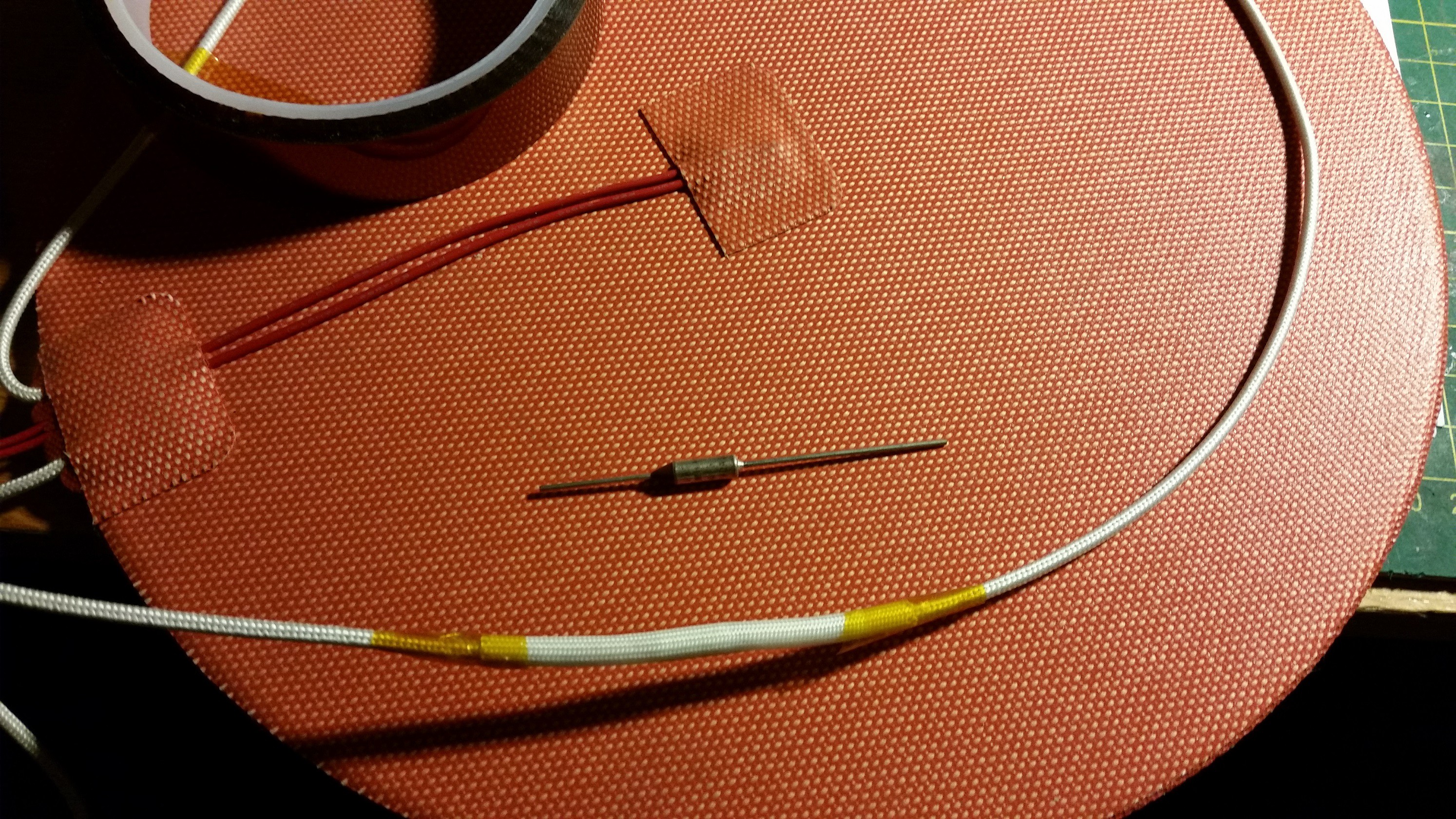
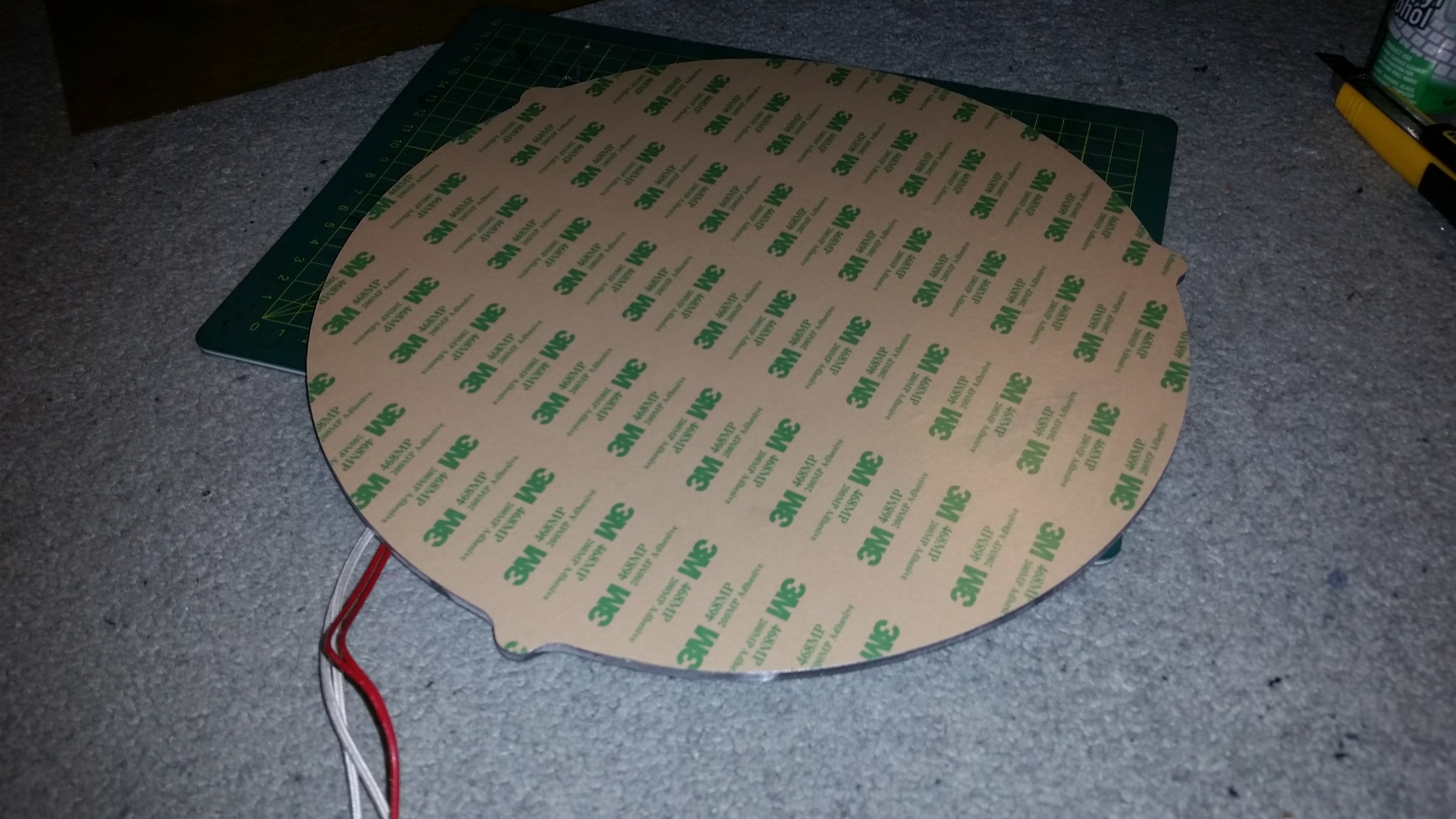
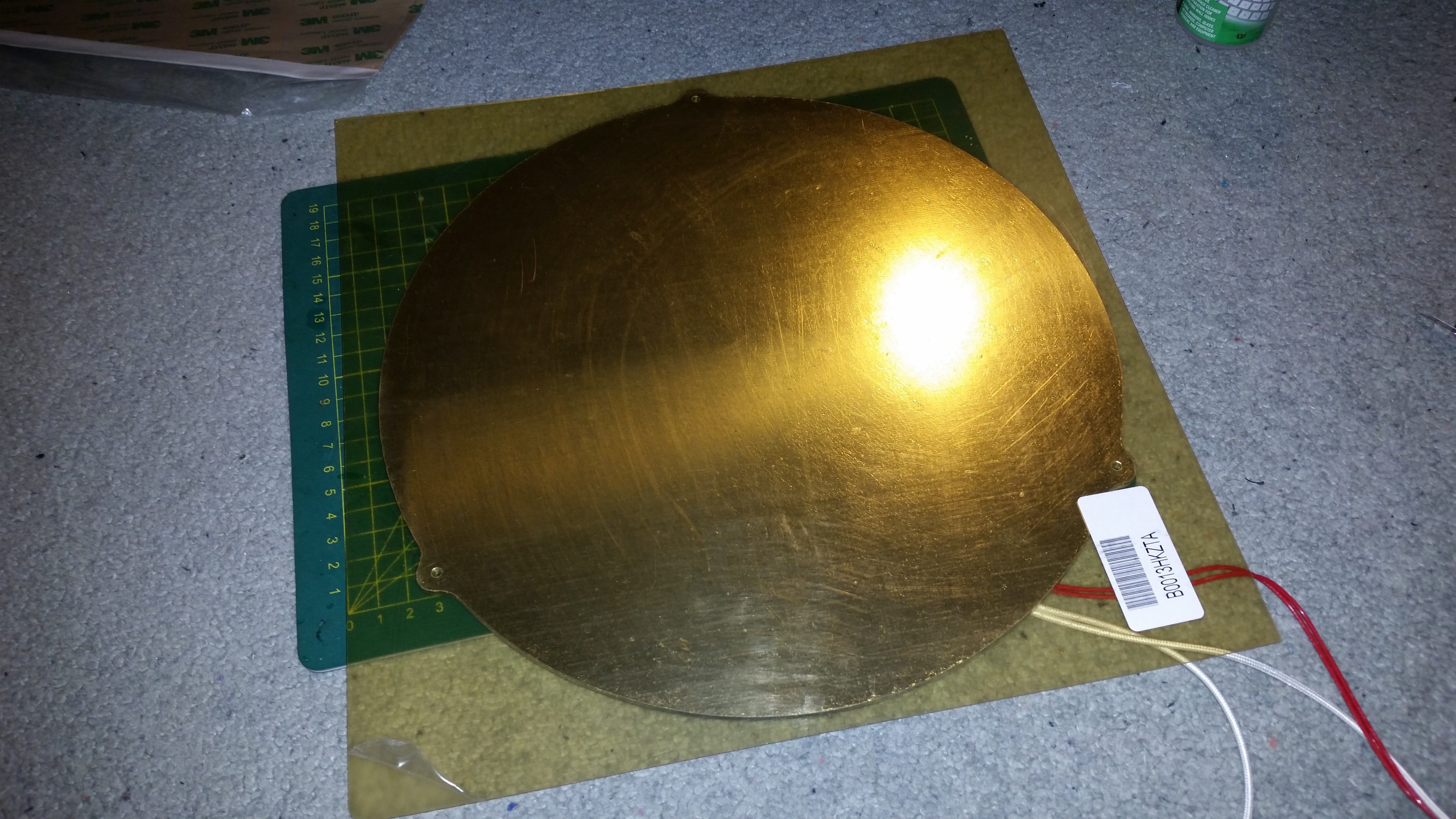
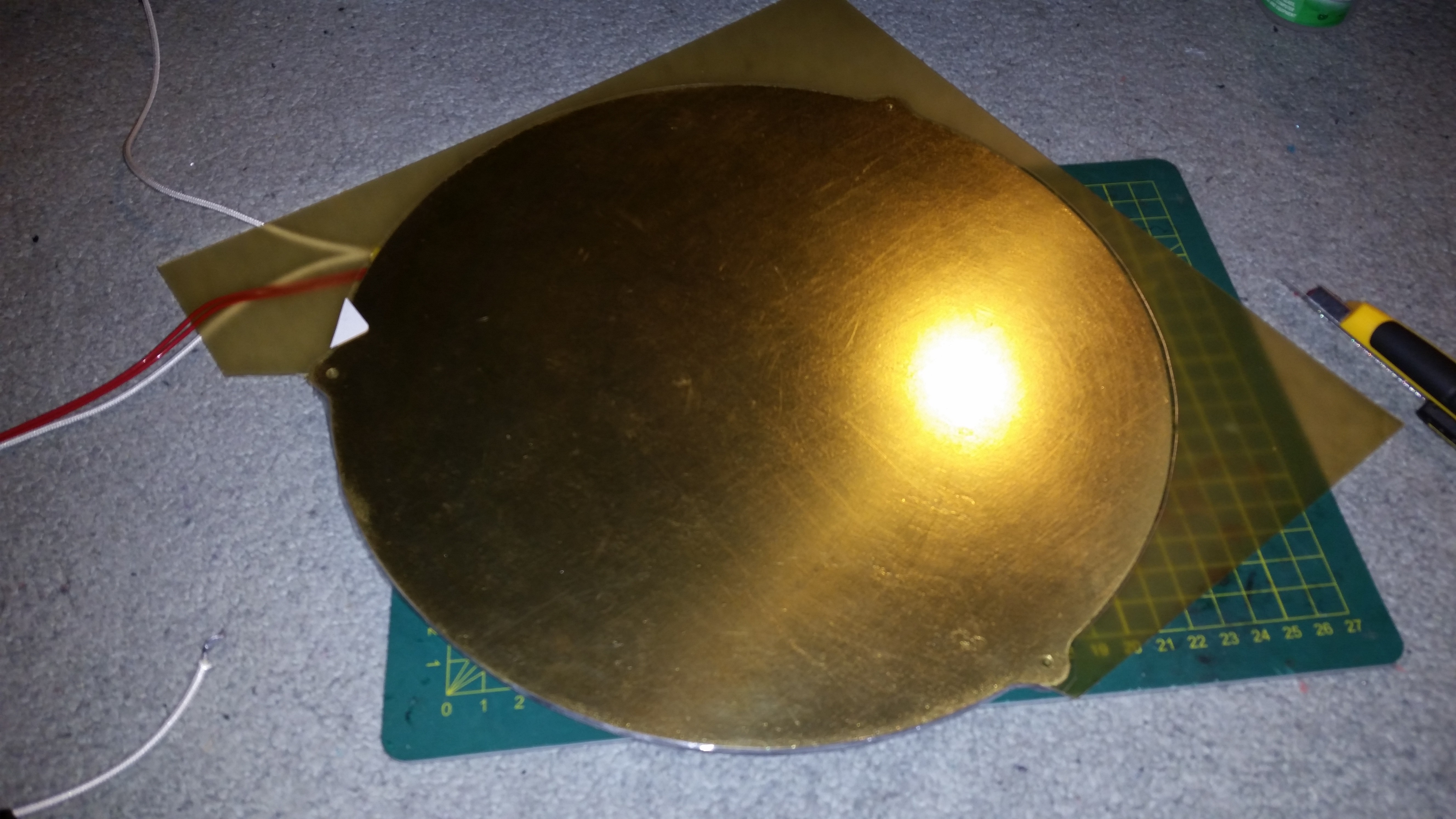
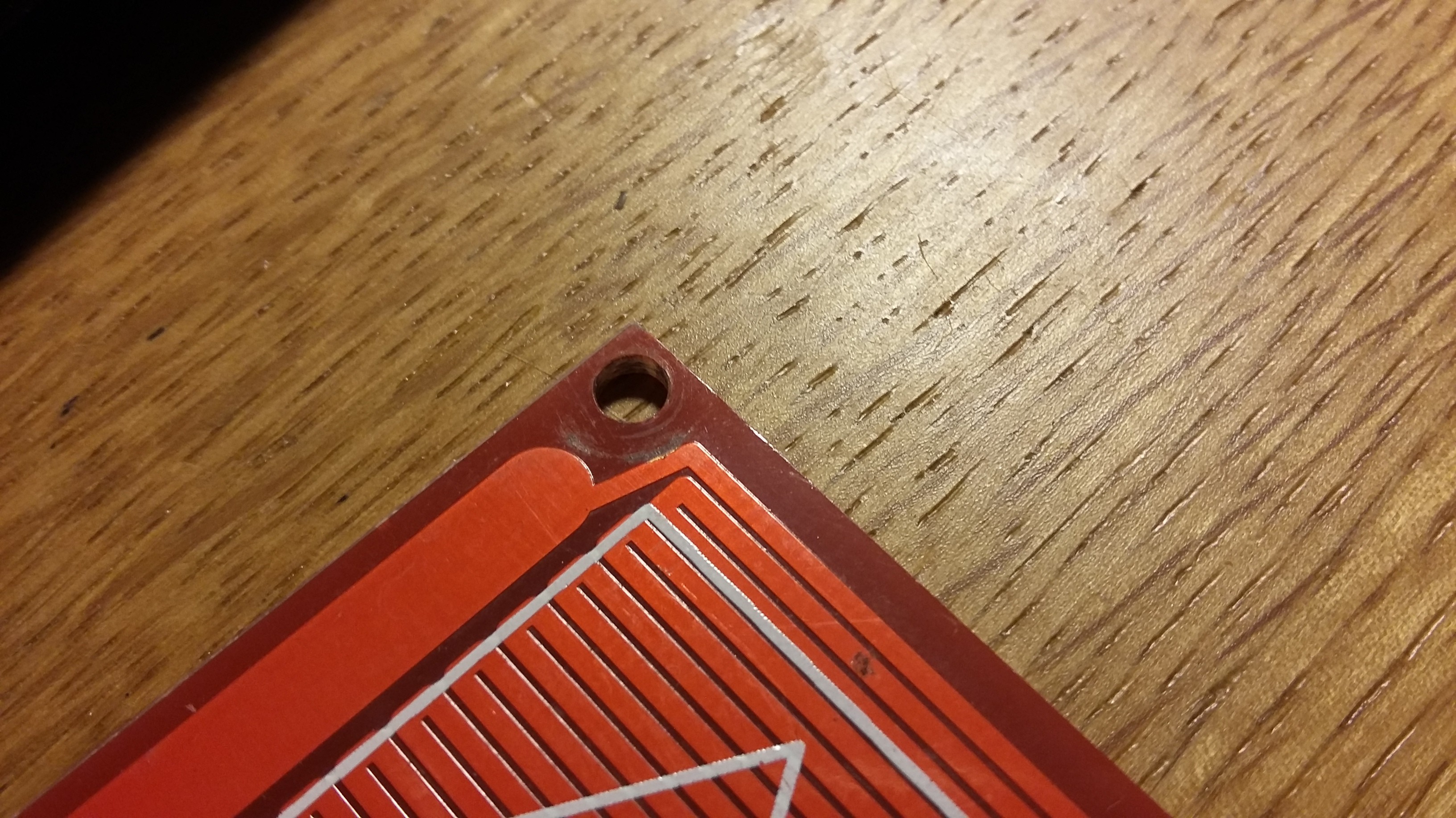
Print Surface |
Aluminium heated bed laminated with PEI Sheet 230v Silicone Heater controlled via Solid State Relay (SSR) |
|
Layer Height |
0.05mm to 0.4mm (0.002in to 0.015in) |
|
Filament |
1.75mm PLA, ABS, PETG and more |
|
Hot End |
E3D V6 with 0.4mm nozzle (with V6.1 block and nozzle sock) |
|
Cold End |
E3D Titan Extruder, Bowden Tube |
|
Controller |
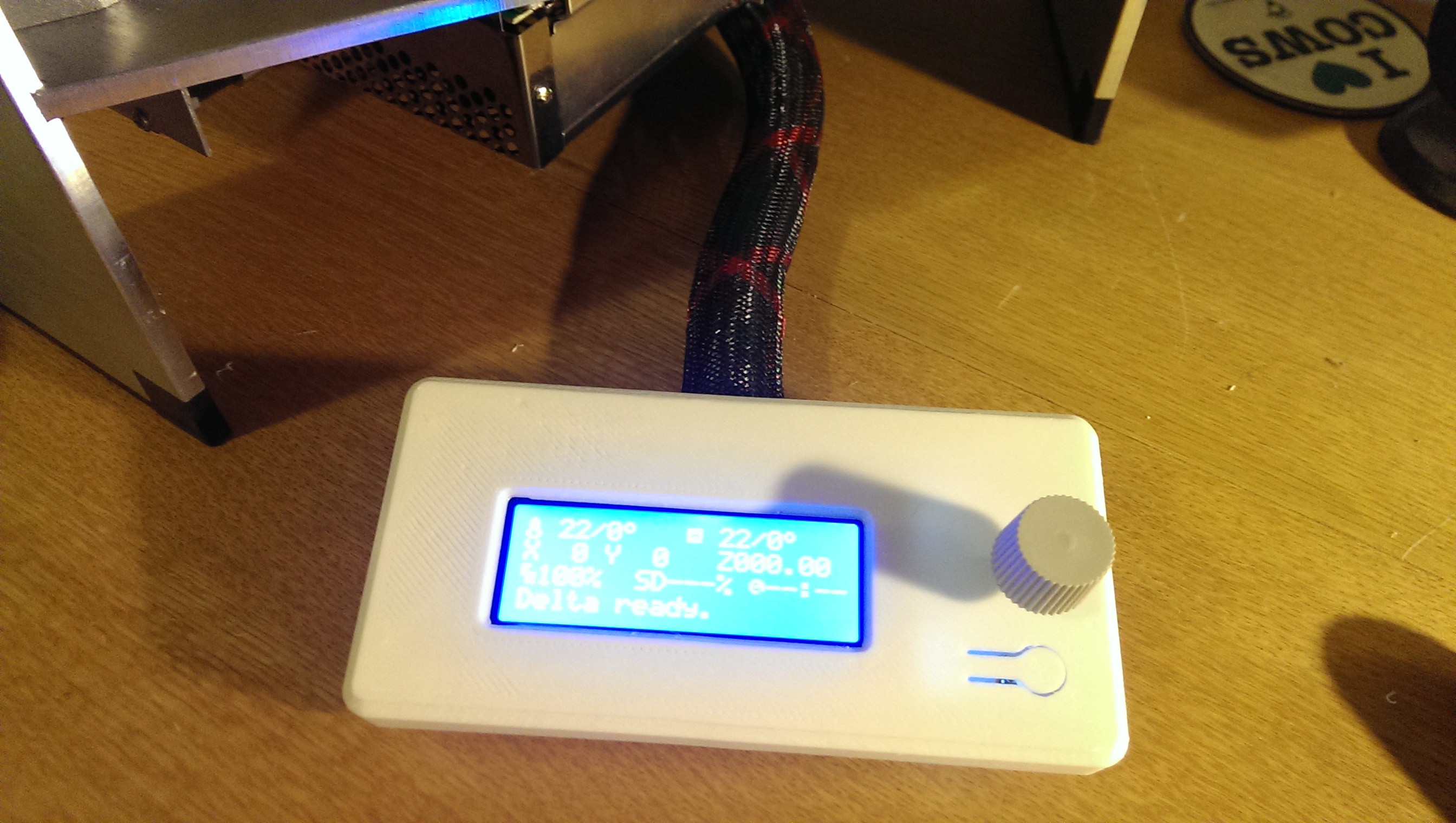
MKS SBASE running Smoothieware with GLCD screen |
|
Power Supply |
12V 30A |
|
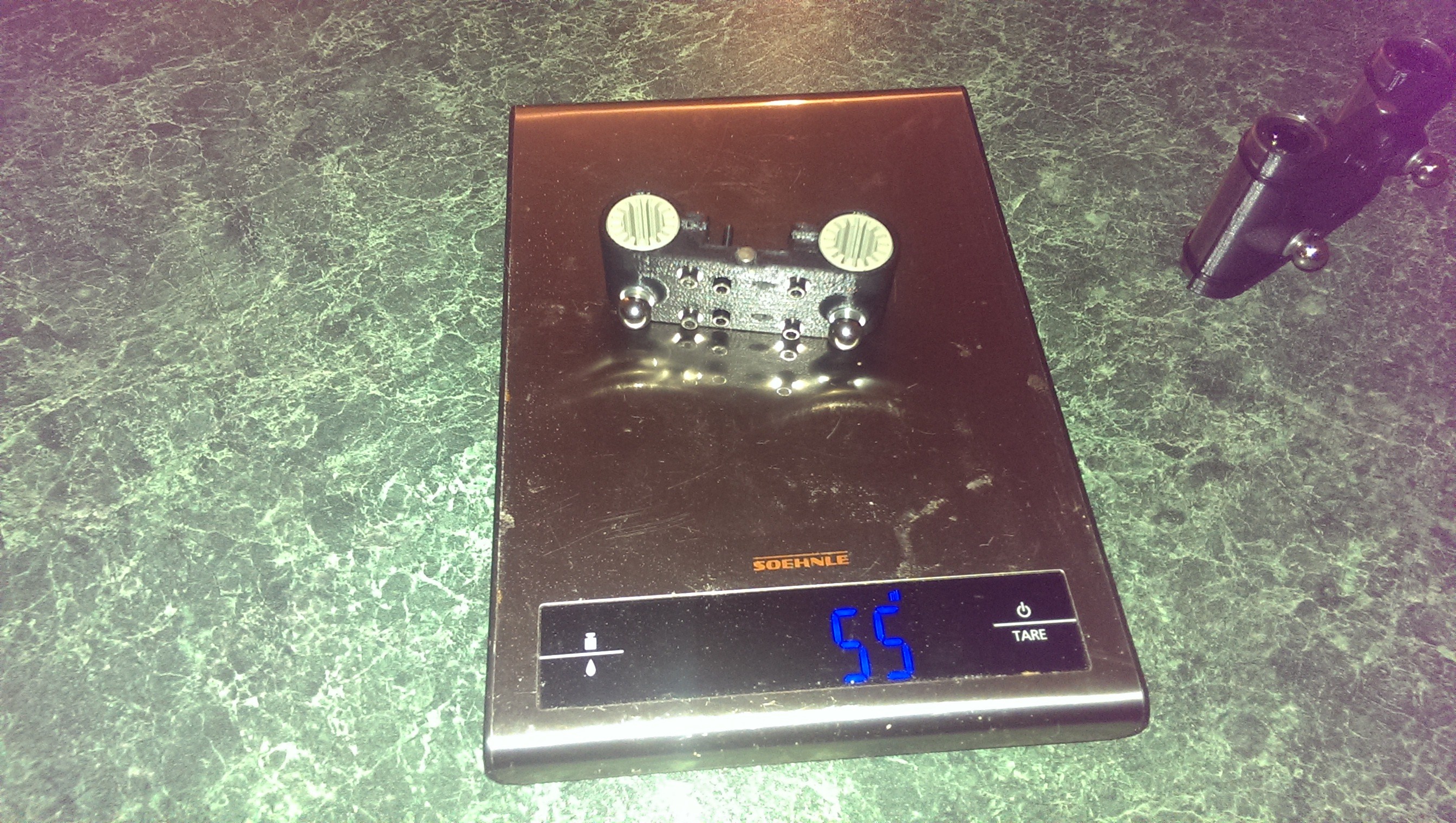
Weight |
17 kg (37.5lbs) |
|
Overall Dimensions |
412mm x 355mm x 896mm (16.2in x 14.0in x 35.3in) |

 Dylan Radcliffe
 Eno423
 Saabman
 Luke Brandon
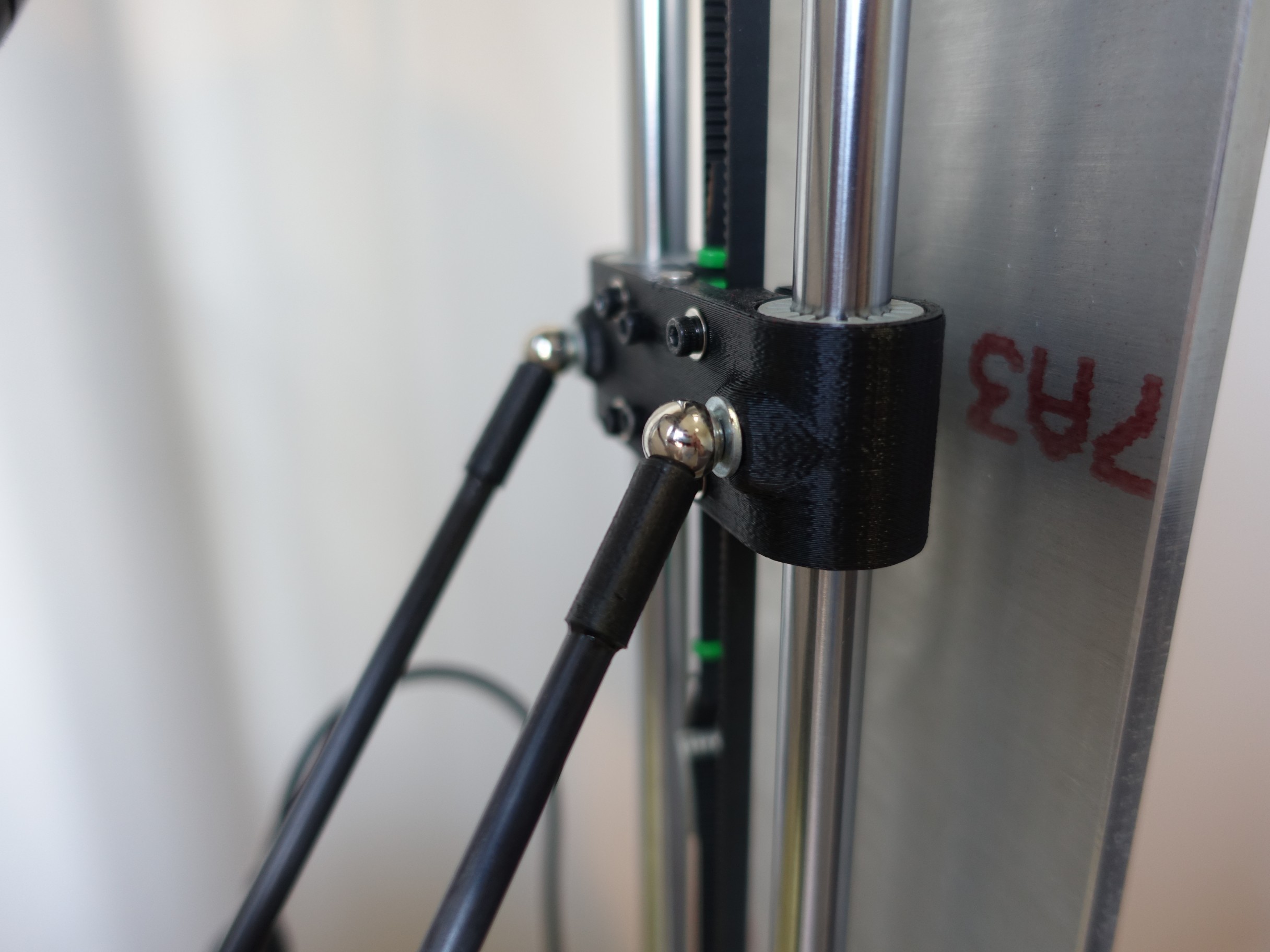
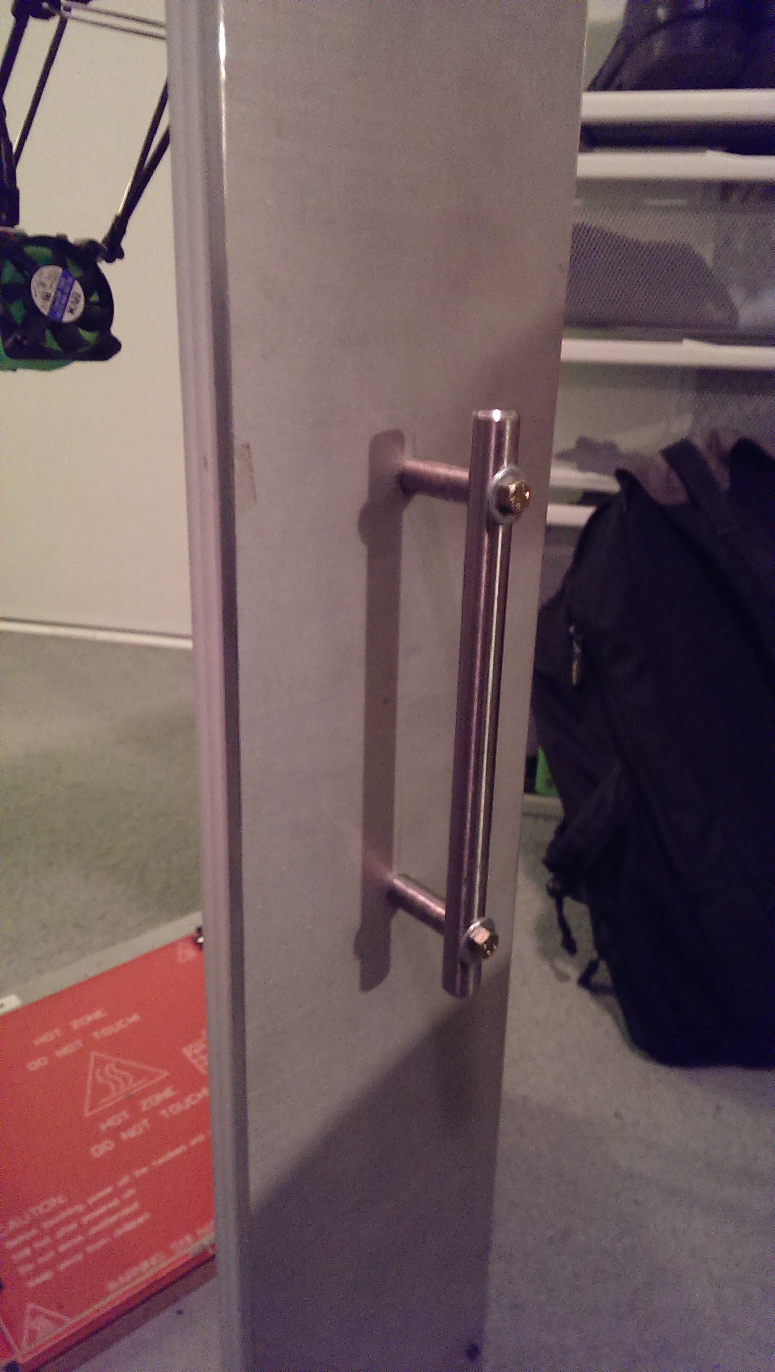
Does this flex or vibrate significantly? Wondering whether it would be beneficial to add stiffeners to the verticals (making "T" or "I"-beam shapes), and braces where the verticals meet the top and bottom plates.