 Myles Eftos
Time to unshelve this project.
I have been doing some research into PCB mill designs over the past couple of weeks, and I've decided to move from a fixed bed, to a fixed gantry design (based heavily off the cheap Chinese machines). This means I only need three motors, and three lead screws rather than 4 of the original design.
I'm giving myself a $250 budget for the conversion.
Due to the existing hardware that I want to reuse, the actual build area for this machine will be relatively small, so I'm hoping that will help with the rigidity of the system (smaller builds should be stronger than larger ones). Given that this PCB millgets decent results with a wood base, I'm feeling pretty confident we can get some good results with this.
So, a stock take of what I have from the Makibox:
- 4 x NEMA 17 sized motors (Longs: 17HS 42BYGH 1.8°)
- 1 x 218mm T8.8 (8mm diameter, 8mm travel per revolution) trapezoidal lead-screw
- 1 x 165mm T8.8 trapezoidal lead-screw
- 1 x 147mm T8.8 trapezoidal lead-screw
- 2 x 226mm x 4mm steel rod
- 1 x 170mm x 4mm steel rod
- 1 x 164mm x 4mm steel rod
- A bunch of cap hex screws
- Plastic couplers
- Plastic anti-backlash nuts
The plastic anti-backlash nuts are surprisingly good - I can't detect any backlash (with the naked eye). The injected plastic piece has some thread that acts as a preloader - quite clever really. Regardless, I decided to order some metal anti-backlash nuts - I'm not sure how the plastic will hold up to the additional force of milling.
I also ordered some aluminium couplers (to replace the plastic ones), LM4UU Linear bearings (to slide on the steel rods), and round bearings to hold the lead screws. Total cost so far: $79.68.
Everything else looks useable (at this stage) - I'm a bit concerned that the steel rods aren't straight enough, but I'll run with them for the moment.
I'm going with 4040 aluminium t-slot for the frame. I've found a Melbourne based supplier so I should be able to get high-quality stock quickly (and cut to size!). But before I order them, I'm going to design the mill in Fusion 360 so I can test for fit and size.
You can see the render of the Y-axis here:
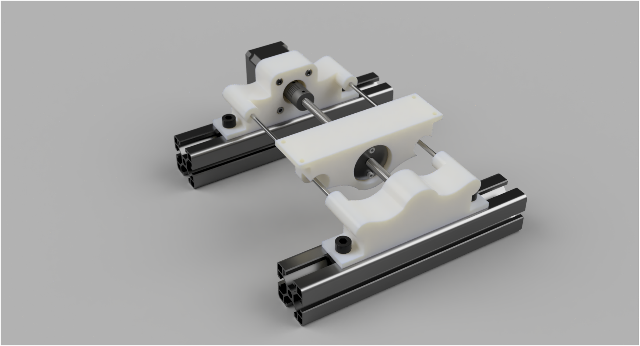
The X-axis will be basically a copy, rotated 90 degrees. The Z-axis will still need some thinking.
The motor bracket, bed and bearing holder will be 3D printed on my Lulzbot Mini. This is is the cause of the weird design - it needs to fit in the 150mm x 150mm build envelope of the 3D printer.
The design should allow a Y-axis travel of around 156mm. I still have to work out the X-axis travel.
Discussions
Become a Hackaday.io Member
Create an account to leave a comment. Already have an account? Log In.