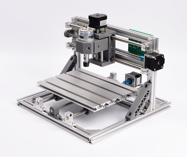
 Myles Eftos
I’ve been iterating the Y-axis in Fusion 360. A common design I have seen on other moving-bed designs is four linear bearings - one bearing at each corner of the bed. The problem with this design is you lose the distance between the bearings in travel. Since I have only have a maximum of 165mm on this axis, I didn’t want to lose too much to dead play.
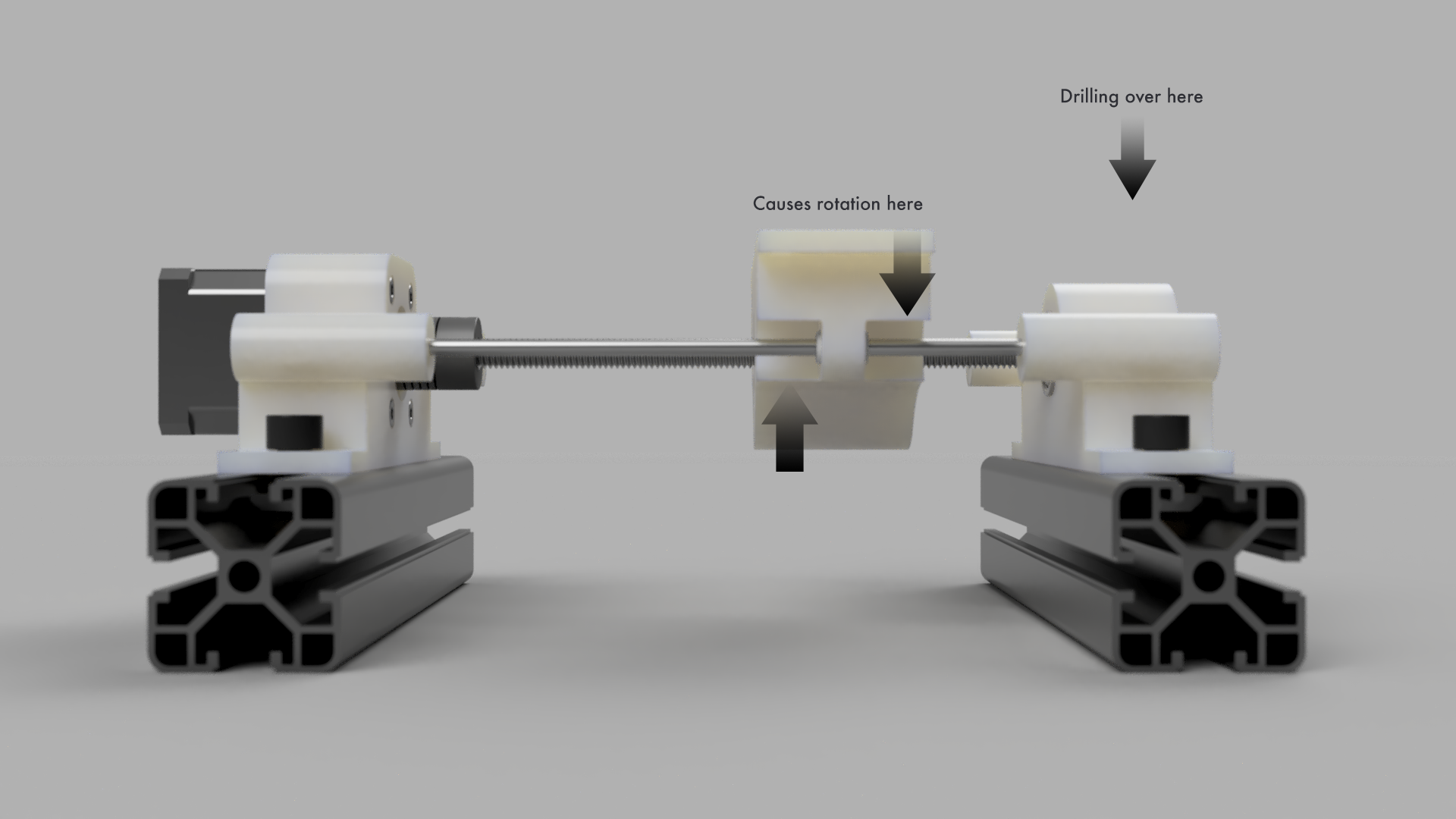
My first thought was use a single bearing on each side, introducing a minimum lost travel of 12mm (the width of the bearing). This looked like it would cause rotation problems, though - especially when dive cutting in the outer edges of the build area.
I went back and looked the parts I could salvage from the Makibox, and it turns out I have four 170mm linear rods at my disposal. This means I can create a passenger carriage - one that isn’t driven by the lead screw, but instead is pushed along it’s rails by the bed itself. This design gives four points of contact, eliminating the radial moment of the two bearing design (Note: this doesn’t deal with linear rod or bed flex, just the rotation issue). The disadvantage is the base is now double the size, but as the bed would have moved outside of the frame envelope during operations, it’s not that big of a deal.
Here is a render of the Y-axis. If you imagine a bed on top of it, attached to the two carriages - the left (driver) carriage is driven by the lead screw, while the right (passenger carriage is pushed by the bed. (I tried making a video, but the Fusion 360 animation workspace doesn’t support animating joints!)
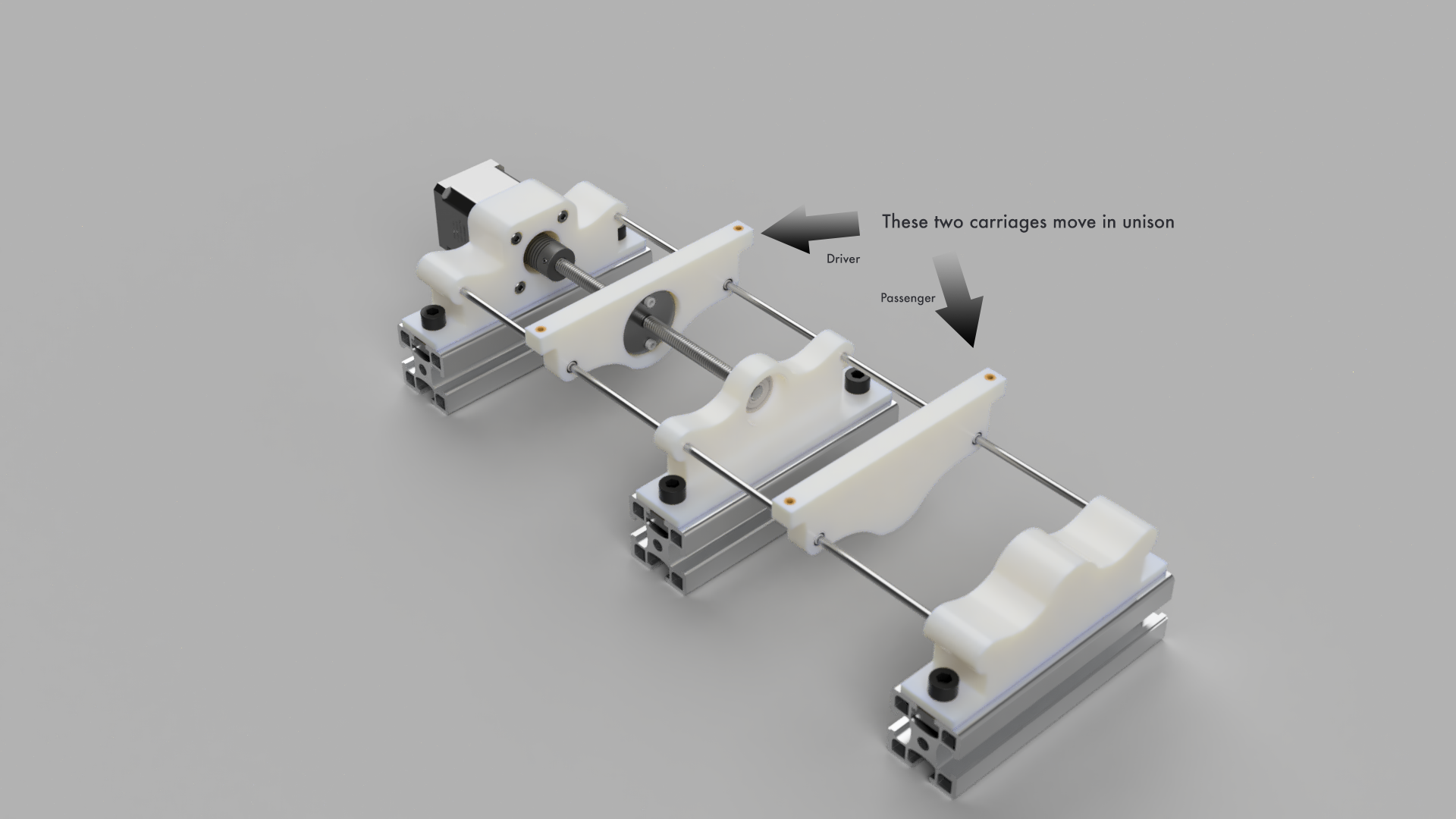
The Y-axis will have a 131mm travel - the loss is 7mm from the ball bearing, 7mm from the coupler and 20mm from the anti-backlash nut.
A couple of side issues I still need to work out:
- The mount holes for the anti backlash nut are too close to the shaft, so I can’t heat fit brass inserts to screw in to - I may have to thread the plastic. I may be able to find some small nuts to secure it. Ideally once the mill is working I’ll be able to machine a bracket from a small plate of aluminium
- I have brass inserts in the carriages because I initially thought I would screw the bed down from the top - making replacement of the spoil board easier. This may not be an actual problem though - I’m not sure how often the spoil board needs changing. I may just make them screw holes, and be done with it. I have to think about it a bit more.
Next up: the X-axis
Discussions
Become a Hackaday.io Member
Create an account to leave a comment. Already have an account? Log In.