 Myles Eftos
In my previous post, I realised that the 4mm steel rods weren’t going to cut it when milling – they had way too much play, so I promptly ordered two 200mm linear rails (for the X-axis), two 400mm linear rails (for the Y-axis) and two 150mm 12mm linear rods and bearings (Z-axis).
The 200mm slides and the 150mm rods arrived promptly, but there was a delay on the 400mm slides. That, plus me needing a fair chunk of time to measure, drill and tap a bunch of holes meant I parked the project for a couple of weeks.
I finally managed to get a couple of days off while I changed jobs, so I arranged a hot date with my drill press.
The Tappening
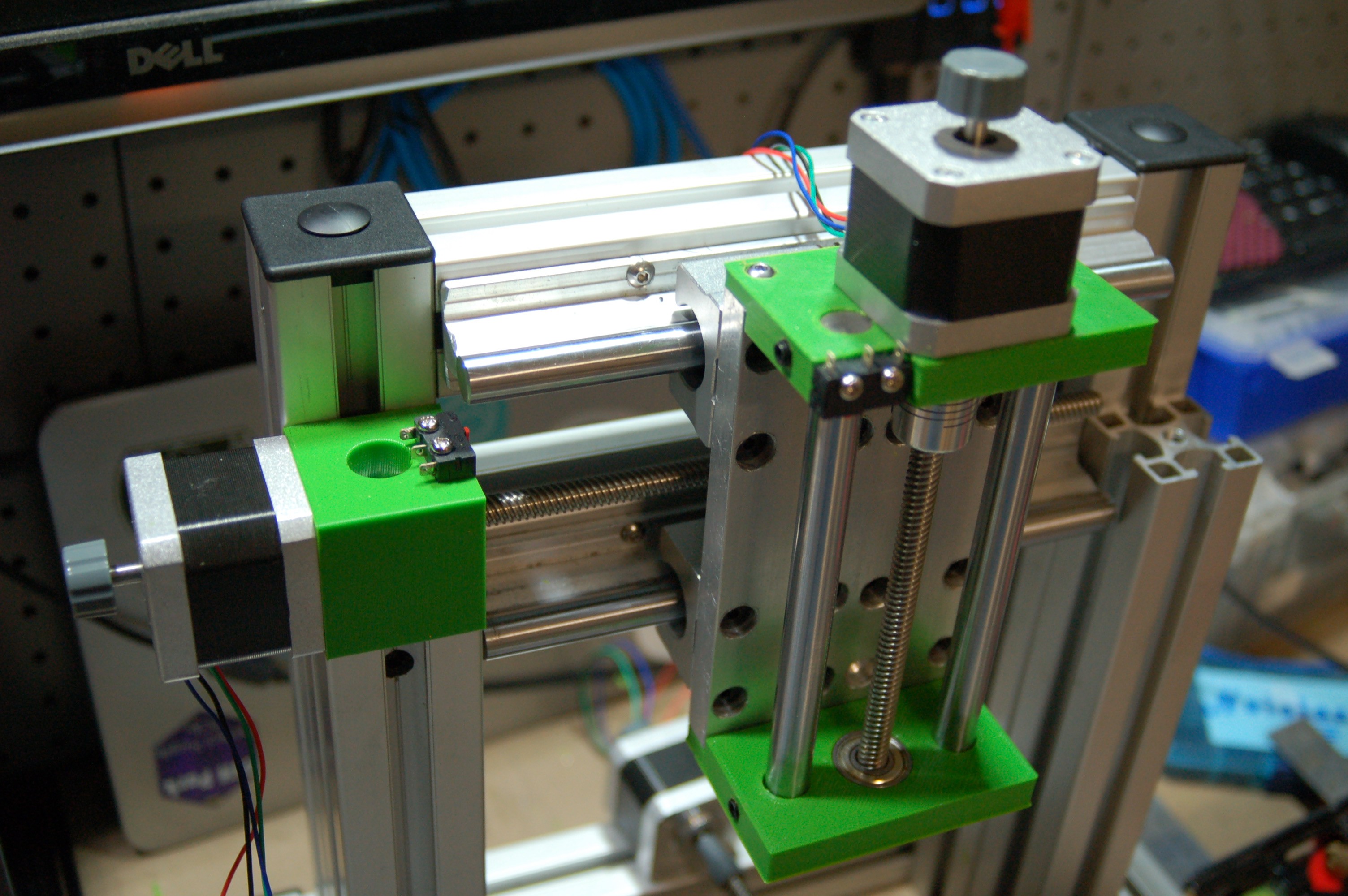
The x-axis slide has four mounting screws which required tapped holes to be drilled into the two horizontal 4040 aluminium extrusions. Now, I’ve not done much in the way of metalwork since year 11 (some 18 years ago) and it took me ages to mark, drill and tap the holes. This was a good warm up for Z-axis face plate.
The face place required a total of 20 holes: four 2.5mm tapped to an M3 and sixteen 5.5mm counterbored to 10mm. It’s not the neatest job in the world, but it is functional. And I only misaligned one hole, which am actually amazed by.
I have stuck with 3D printed anti-backlash nut holders, with the intention of milling them out of aluminium once the mill is completed. This is why they are the shape they are – so they will be easy to mill.
The Z-axis
The same applies to the Z-axis end caps – I added grub screws to hold the linear rail which adds some rigidity – and they will be especially helpful on the milled version.
After doing a fit test it became clear that the motor couplers were too springy (the ones I bought are designed to deal with things being out of alignment) so I’ve now ordered some rigid ones that will eliminate any slop.
I 3D printed a Z-axis carriage to test fit, but it became clear it was too big (90mm tall) which meant my Z-axis would be less than my 70mm design goal. I’ve simplified it to be more box like (easier to mill down the track), and reduced the height to 60mm, by cutting down the flange on the anti-backlash nut, and by making it a two piece part. At this point, I calculate a 78mm of travel in the Z direction.
I now need to fabricate the aluminium face part part, which the carriage and the spindle screw in to.
Discussions
Become a Hackaday.io Member
Create an account to leave a comment. Already have an account? Log In.