 Myles Eftos
The version of the Makibox that I purchased came with a printrboard, however I fried that years ago. Makibox shipped me a replacement Print5D D8 controller.
I knew very little about this board, and I wondered how I was going to adapt it for CNC use.
I had some questions:
- How do I send it G-Code? Do I need to use the software that came with the Makibox?
- Controlling the three axes and endstops was easy, but how would I run the spindle?
- After more research about milling PCBs, I found out that using a bed levelling algorithm would give the best results – could the board do that?
After some googling, I found that a kind user had archived all of the original Makibox forums. A post about the D8 firmware lead me to the Makible bitbucket account, which not only housed the original firmware source, it also had the schematics!
Some more random googling yielded another interesting tidbit of information: Marlin has hardware definitions for the D8 board.
The original firmware (from 2014) was based on Sprinter which was forked and became Marlin.
Fun fact: Marlin is also what my Lulzbot Mini uses.
Sending G-Code
I know had an answer to question 1: Marlin appears as a serial device that you can simply send G-Code to. If you have screen installed on your *nix like computer you can just connect (by passing the path to your TTY device) and directly enter G-Codes – although using a G-Code sender is easier.
After wiring up the endstops and motors (only the X and Z because I’m still waiting on the slides for the Y) I entered G28 which runs the homing routine. It worked!
The next problem to solve was driving the spindle. The Makibox schematic revealed the drive circuit for both the hotbed and hotend use a MOSFET to switch a 24V line (using PWM). The MOSFET is rated to 40A, which is plenty to run the 5A spindle I have.
Welcome to 2018
This current firmware is ancient, is tuned to the Makibox build area and doesn’t support autolevelling or controlling a spindle, so I needed to upgrade to the latest Marlin. This was far easier than anticipated.
The board is based on the printrboard which is based on the teensy 2.0++, so the first step is to load the teensy board definitions into the Arduino IDE. Unfortunately, this isn’t via the usual method of adding a URL to the board manager – there is a installable which manually handles installation, and adds a bunch of wizards that, if you have done any Arduino development, kind of get in the way.
Regardless, it allowed me to choose the teensy 2.0+ as a build target.
Next, I modified the configuration.h and configuration_adv.h file with the new build area parameters, and set the various options. A number of these settings hadn’t changed since Sprinter, and I was able to just copy the values. I did have to modify a non-configuration file to allow pin 15 to be defined as a PWM pin.
After compiling, I put the board in bootloader mode by placing a jumper over the boot pins and clicking reset.
Once in bootloader mode I erased the EEPROM and uploaded the binary hex file via dfl-programmer.
sudo dfu-programmer at90usb1286 erase
sudo dfu-programmer at90usb1286 flash Marlin.hex
The spindle parameters took a little bit of trial and error to get right:
To calculate the SPEED_POWER_SLOPE use the formula:
(SPEED_POWER_MAX - SPEED_POWER_MIN) / 255
I decided to use 0%-100% as my MIN and MAX, so the value I needed was (100 – 0) / 255 = .392156863.
Using that range allows me to use different gear ratios and to drive a laser cutter without modifying the firmware.
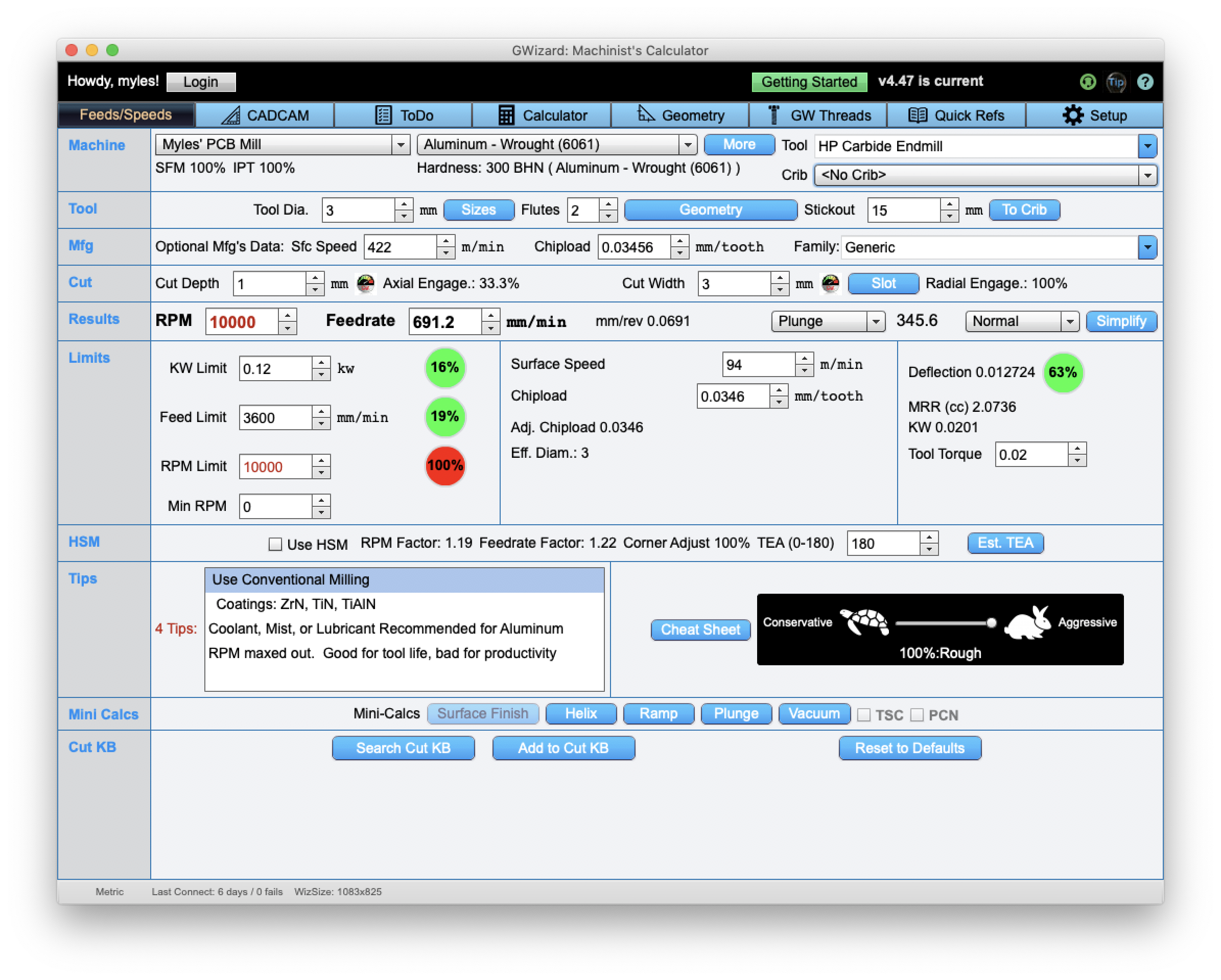
I have purchased a copy of GWizard which calculates spindle speeds and feed rates, and it will output a power percentage based on the profile of the spindle, which makes the calculation easy.
I’m not entirely sure what SPEED_POWER_INTERCEPT is, but I’d guess that it is a way of offsetting the speed. I’m not sure why you would need to do that.
The new firmware has given me the ability to set the spindle speed via M3, M4 and M5 (M3 and M4 do the same thing because the hardware can’t reverse the direction of the spindle), and in theory perform an auto-level – I say in theory, because I don’t have a levelling probe, nor do I have the Y-axis linear slides. I have now followed up with the AliExpress seller to see where they are.
So once again, I’m blocked – but progress has been made!
Discussions
Become a Hackaday.io Member
Create an account to leave a comment. Already have an account? Log In.